17.9. Solar Application scheme I
Loading of pool system from solar collector.
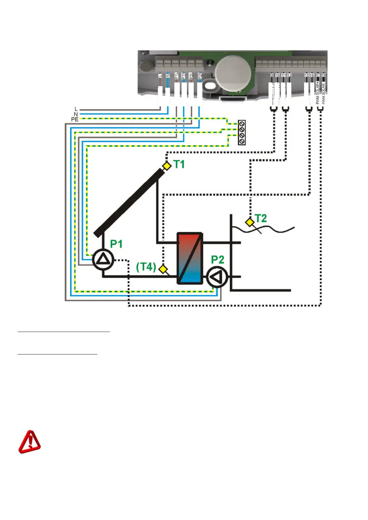
Fig. 17.9 Application scheme I
Installation recommendations
1. For the controller to count heat output, it is required to install additional CT6 sensor directly on the
return from the pool exchange, and connect it to T4 measurement input.
Setting recommendations
1. With the use of additional T4 sensor, the controller allows effective controlling of P2 pump that will
be started, when the temperature of return from exchanger reaches dTP2 value.
2. At long pipe lengths (between collector and exchanger), setting of dTP2 value lower than it results
from losses incurred in the collector-exchanger section will prevent starting of P2 pump, even at
high temperatures in the collector. This setting must be selected specifically to each installation.
3. During anti-freeze function, the exchanger pump will work longer than the collector pump by
double tDLY time. So select this parameter value that after P2 is stopped, the temperature of
glycol in exchanger is not lower than 0°C, as it may damage the exchanger. If there is a risk that
such situation may happen, switch off antifreeze function for the pool system.
Antifreeze function in pool circuit (with priority) may be used only at high awareness. Wrong
settings or unfavorable conditions may damage the exchanger. Always consider all factors like,
e.g., solar work fluid with below-zero temperature in the exchanger.