15. TECHNICAL DATA
Measurement inputs
(low-voltage)
Collector temperature input (T1)
Other inputs/outputs:
(low-voltage)
Output (H) 5-6V/0,1A (DC)
Output PWM for
controlling the solar pump
(only P1)
PWM freguency signal: 200Hz
Signal level: 5V
Digital: 5÷100%
Output P1: 230V/ max 0,5A (AC)
Output P2: 230V/ max 0,5A (AC)
Controller: 230V(AC), 50Hz. I=1.02A*
not more than 0.5A(AC)/output
0° ≤ Ta ≤ 40°C, humidity 10-90%, without condensation
* Power intake only by controller is 0.02A (1,5W)
Table of temperature measurement accuracy:
Pt1000 class B (CT6 and CT6w)
* at ambient temperature of 23°C
** in scheme H, L
16. INSTALLATION
The controller is designed for operation in the
environment where only dry conductive
contaminations may be present (2 degree of
contamination according to PN-EN 60730-1).
In addition, the controller may not be used in
water condensation conditions and it may not be
exposed to water.
The unit software does not ensure
required protection level that must be
assured by external protections of the
solar system.
16.1. Installation of the controller
The controller is designed for vertical wall-
mounted installation. External circuit wires are
supposed be lead on surface. Mounting hole
locations are presented as in the casing. Hole
spacing dimensions are presented also in Fig.
16.2
Wires that enter the controller must be
secured at entry locations.
Before opening the unit casing,
disconnect power supply. The unit
installation must be done at disconnected
The unit has any fuse replaceable by the
installer or use. If the fuse was burnt
during installation or operation, it means
damage of the unit. Send the unit to
authorized service for repair.
Controller must be installed by qualified
and authorized technichian in accordance
with EN 60335-1 standard.
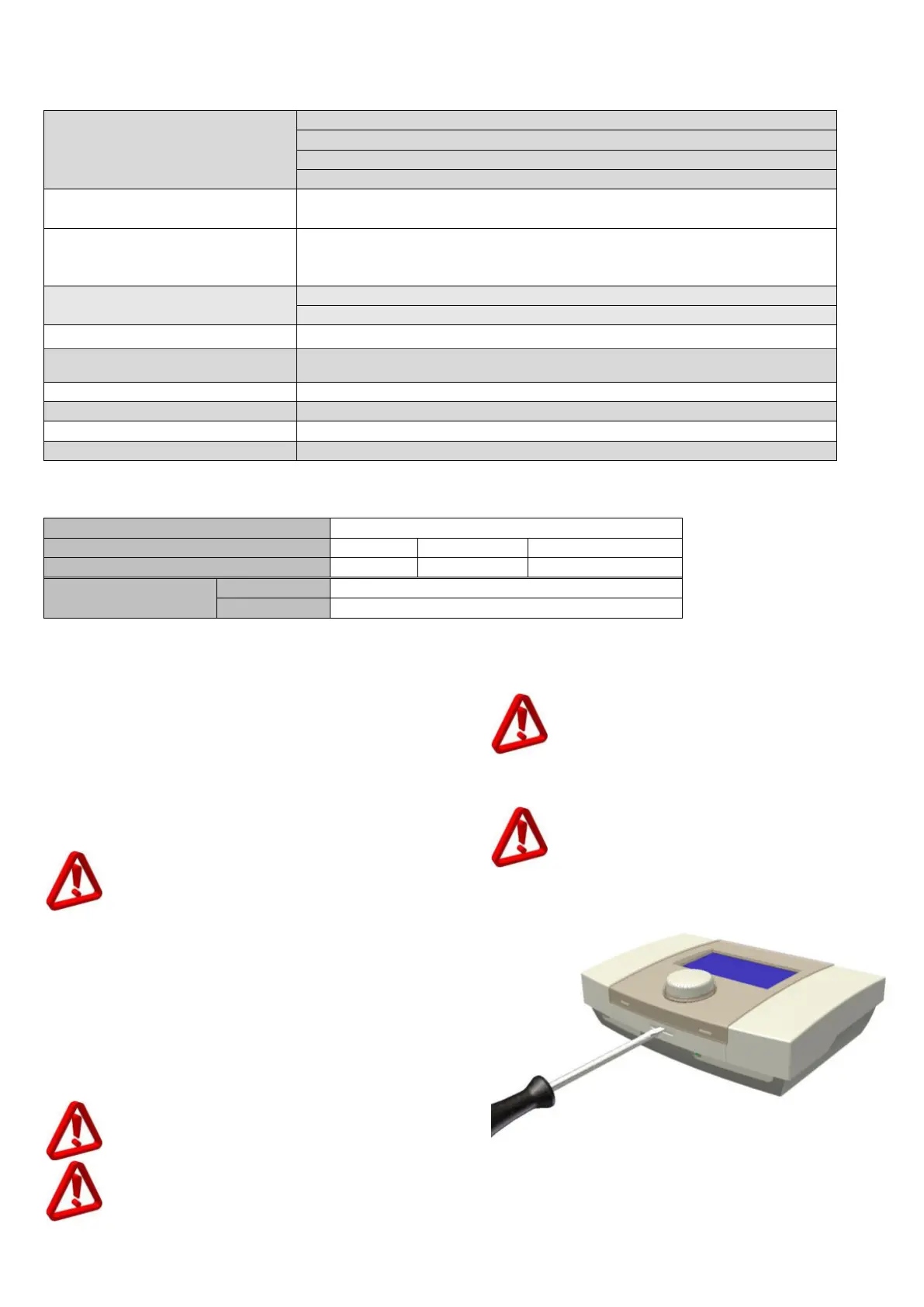
For how to open the unit casing see the picture
below.
Fig. 16.1 Casing opening