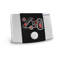
16.2.2. Power supply connection
The controller is designed for supply
voltage 230V~, 50Hz. Supply is connected to
terminals L, N. Electric connection diagram is
presented in Fig. 16.5. and Fig. 16.6.
230V supply wires must be lead so as
their contact with sensor and other low-voltage
cabling is prevented, additionally, all cables may
not contact surfaces with temperatures that
exceed the cables operating temperature limits.
The controller has no PE protective
connector, because the controller itself does not
require grounding. PE terminals of the pump shall
be connected with PE of supply network,
according to periphery instructions and regulation
concerning electric systems. Proper electric
installation method is responsibility of the
electrician. It is recommended to connect PE
circuits through external screw connector, as
presented in diagrams.
Fig. 16.5 Power supply connection
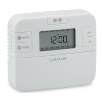
Fig. 16.6 Connection of pumps
The P2 pump must be connected in the same
way as for the P1 pump except that the
controller does not control the P2 pump.
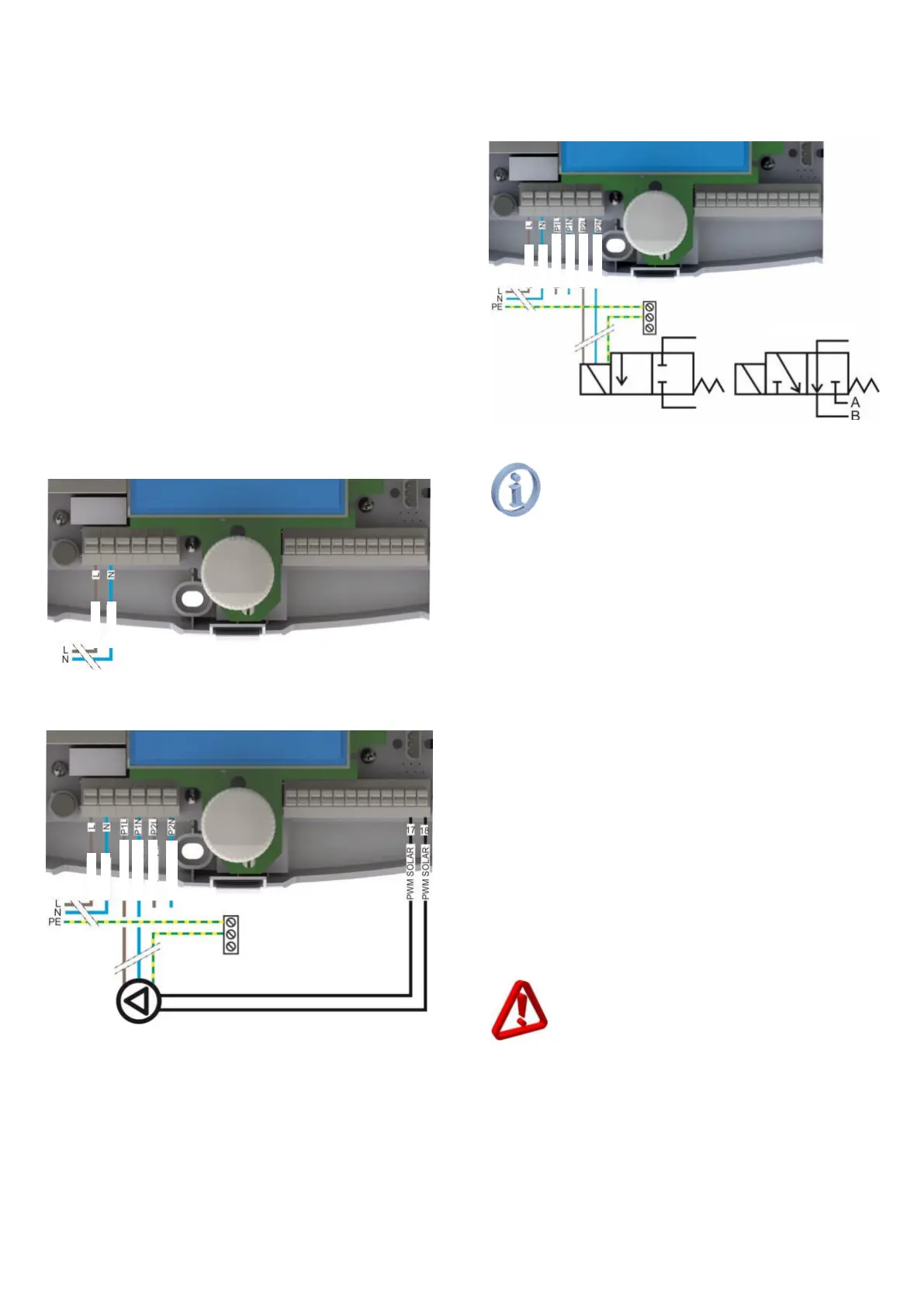
Fig. 16.7 Electro-valve connection
The connection shown in fig. 16.7
requires electro-valve coil adjusted to
~230 voltage.
16.2.3. Connecting the PWM signal of the
solar pump
The device is adapted to co-operate with the
HIGH EFFICIENCY solar pumps controlled PWM
signal according to EN 60469. Connection PWM
signal must be in accordance with Fig. 16.6.
16.2.4. Temperature sensor connection
Sensors are provided with two wires:
CT6w 1m long, silica wire;
CT6 2m long.
If you need longer cables, use 0.5÷1.5mm
2
cable
not longer than 30 meters,
and connection points must secured against short
circuit and humidity. Take a note that when
extending the line with additional wire the sensor
circuit resistance increases and it may cause
errors in measurement.
Such errors may be adjusted by the wire
length compensation function described in menu
I/O Configuration. Compensation method is
described in section 19.2.1.
CT6w sensor is provided with special
high-temperature silica cables, it must
not be replaced with CT6 sensor, because
of possible insulation damage when the
collector temperature is high.