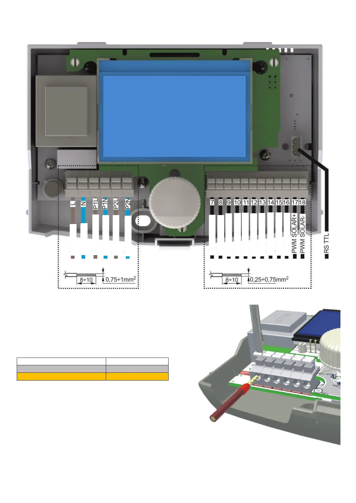
16.2. External circuits connection.
Fig. 16.3 Controller inside view with terminals
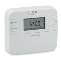
16.2.1. Use of connectors
The controller is provided with spring loaded
terminals suitable for reception of wire with an
end sleeve.
The table below includes permissible size ranges
for wires connected to the controller terminals:
* For installations with bare wire cables the maximal size is
1.5mm
2
For good connection between the terminal
and cable, insulation and sleeve free length
should be in the range of 8÷10mm.
To place wire in terminal press the terminal
push with a flat screwdriver, insert the wire end
(with a sleeve on) and then release the push.
Fig. 16.4 Using clamped terminals