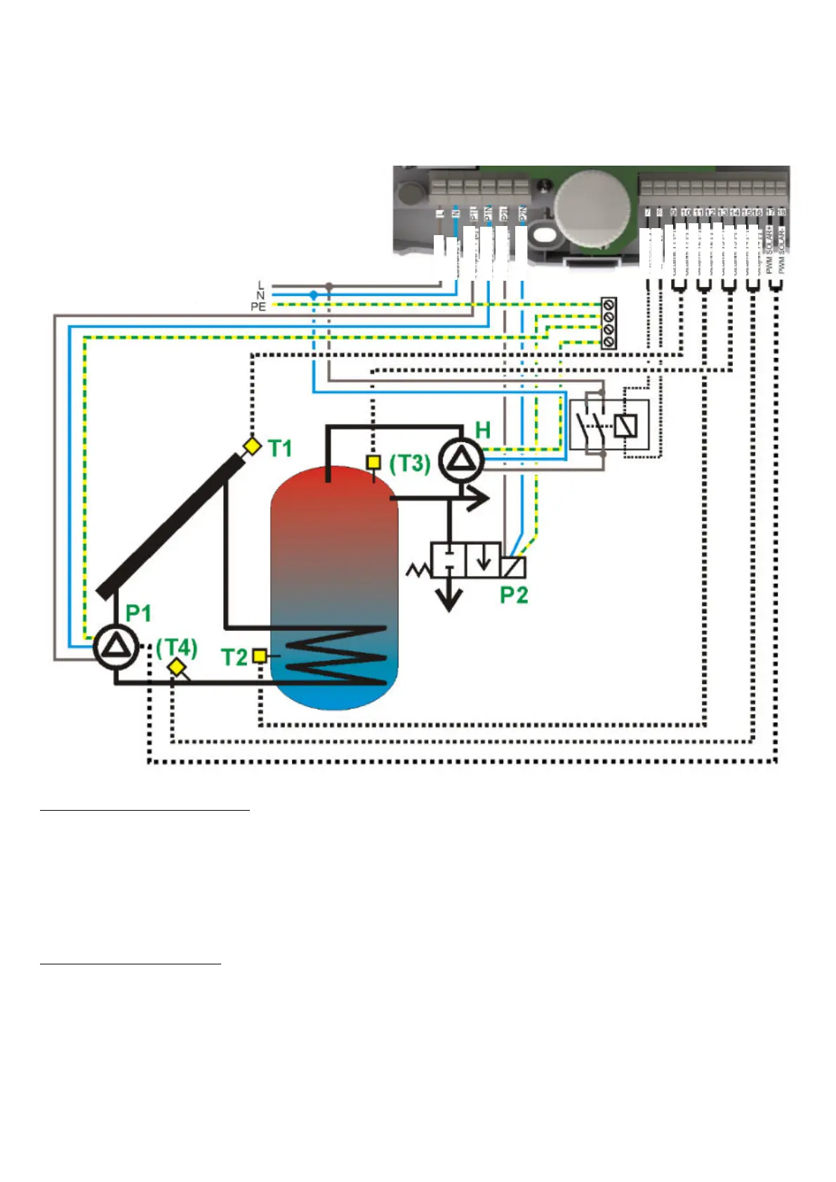
17.3. Solar Application scheme C
Loading of DHW reservoir from a solar panel with additional function of heat discharge to drain
system, when the reservoir maximal temperature (TDHWmax) is exceeded. In this layout, T3 sensor is
optional and its connection is not required. Electro-valve must be connected to P2 pump outlet.
Fig. 17.3 Application scheme C
Installation recommendations
1. For the controller to count heat output, install additional CT6 sensor on the outlet of lower pipe coil
from DHW container and connect to T4 input. The sensor must be installed possibly near the
connector pipe.
2. T3 sensor shows temperature in upper part of the container, its connection is not required.
3. Connect the circulation pump to the H output via the relay. It is necessary to use a relay type
6VDC RM85-2021-35-1006.
4. Discharge valve coil connected to P2 output must by adjusted to ~230 voltage, see fig. Fig. 17.3,
otherwise the valve should be controlled indirectly by an additional transmitter.
Setting recommendations
5. Heat discharge valve works until T2 drops below TDHWmax-HP2. Do not set HP2 value too high
as this result in large heat discharges.