SAMWONTECH
1st Edition of TEMP880S IM : Sep. 21. 2005 Page 48 / 101
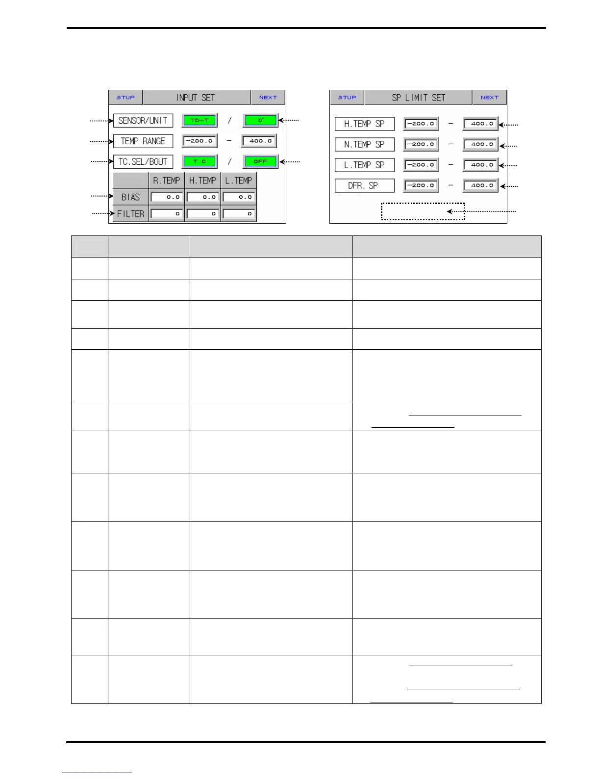
2.12.1 INPUT AND INPUT REVISION FOR SECTIONS
2.12.1.1 INPUT SENSOR SETTING
Diagram 2-46. Input Sensor Setting Diagram 2-47. SP LIMIT Setting
No. Instruction Contents Additional Explanation
○
1
SENSOR SET Choose input sensor.
○
2
TEMP RANGE Sets temperature range.
○
3
TC SELECT
Chooses RJC use when sensor
input kind is TC.
▶ You can choose T C, T+R, RJC.
○
4
SENSOR UNIT Choose display unit. ▶ ℃,℉
○
5
BOUT
Choose PV motion direction
whenasensor is open.
▶ UP : PV moves up toward sensor
▶ UP : input.
▶ DOWN : PV moves down toward
▶ DOWN : sensor input.
○
6
ALL BIAS
Sets revision value for all ranges
on input.
▶ Refer to 2.12.1.2 SECTION INPUT
▶ REVISION SETTING
○
7
FILTER TIME
Removes noise when measuring
input includes noise of high
frequency.
○
8
High
Temperature
Room SP
Sets upper and lower limits of
TSP,WAIT SP setting range of high
temperature room during program
input.
○
9
Normal
Temperature
Room SP
Sets upper and lower limits of
TSP,WAIT SP setting range of
normal temperature room during
program input.
○
10
Low
Temperature
Room SP
Sets upper and lower limits of
TSP,WAIT SP setting range of low
temperature room during program
input.
○
11
Defrost SP
Sets upper and lower limits of
defrost temperature range during
defrost control.
○
12
HIDDEN
BUTTON
Shifts section input revision
setting.
▶ Displays 2.13 PASSWORD INPUT
▶ screen.
▶ Refer to 2.12.1.2 SECTION INPUT
▶ REVISION SETTING
☞ cannot change sensor kind during operation.
☞ Displays “S.OPN“ when sensor is disconnected. Displays PRESET OUTPUT for Control Output (MV).
○
1
○
2
○
3
○
12
○
5
○
8
○
9
○
10
○
11
○
6
○
7
○
4