EasyManua.ls Logo

Samwon Tech TEMP880S User Manual

Default Icon
104 pages
To Next Page IconTo Next Page
Page #1 background imageLoading...
Page #1 background image
THERMAL SHOCK TEST CONTROLLER
TEMP880S
INSTRUCTION MANUAL
Question and Answer IconNeed help?

Do you have a question about the Samwon Tech TEMP880S and is the answer not in the manual?

Samwon Tech TEMP880S Specifications

General IconGeneral
Input TypeThermocouple, RTD
RTD TypePt100, JPt100
Thermocouple TypeK, J, R, S, B, E, T, N
Output TypeRelay, Current
DisplayLED
Power Supply100-240V AC, 50/60Hz
Operating Temperature0 to 50°C
Storage Temperature-20 to 60 ℃

Summary

TEMP880S Instruction Manual

Thermal Shock Test Controller Introduction

Identifies the product as a thermal shock test controller.

1. Installation Instructions

Safety and Installation Procedures

Covers safety instructions, exterior inspection, installation, and wiring.

2. Instruction Manual

Basic Operation and Screen Navigation

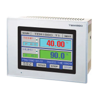
Explains setting buttons, screens, value input, and general operation flow.

1. Installation Instruction

1.1 Safety Instructions and Cautions

Provides essential safety instructions and cautions for users.

Product Safety and Responsibility

Responsibility and Warranty Information

Outlines company liability and product warranty terms.

1.3 Installation

Installation Place, Environment, and Cautions

Details the recommended environment and cautions for installing the product.

1.4 Wiring

Wiring Guidelines and Noise Solutions

Provides general instructions, cable/terminal recommendations, and noise mitigation.

1.4.2 Terminal Wiring Diagrams

2. Instruction Manual

2.1 Setting Buttons and Basic Controls

Describes the function and usage of setting buttons and basic control buttons.

2.2 How to Enter Setting Value

2.3 General Operation Setting Flow Chart

2.4 Initial Screen Details

2.5 Main Screen Navigation

2.6 Operation Screen

2.6.1 Program Stop Screen

Explains the screen shown when a program is stopped.

2.6.2 Program Preparation Screen

2.6.3 Program Operation Screen

Program Operation Screens Overview

Shows operation screens for high, normal, and low temperature room operations.

Auto Tuning Function and Cautions

2.7 Motion Setting Screen

Function and Defrost Setting Screens

Covers settings for outage mode, fuzzy logic, key lock, and defrost parameters.

2.9 Graph and Graph Record Set Screen

Graph Indicator and Time Scale Settings

Shows the graph indicator and allows time scale adjustments.

2.10 Pattern Set Screen

Pattern Set Screen Options

Details pattern setting parameters for Elevator and Damper Type devices.

2.10.1 File Edit Screen

2.10.2 Time Signal Setting Screen

2.11 Display Set

2.12 System Setup Screen

System Setup Options Overview

Lists setup options including input, output, PID, DO config, alarm, comm, and init display.

2.12.1 Input and Input Revision for Sections

Input Sensor Setting Details

Details settings for input sensors, temperature ranges, and units.

2.12.2 Control Output and Transmission Setting Screen

Control Output Setting Details

Details settings for output type, PID direction, and cycle time.

2.12.3 Inner Signal Setting Screen

Inner Signal Setting Parameters

Explains range, delay time, type, and band settings for inner signals.

2.12.4 PID Set Screen

2.12.4.1 PID Range Set

Sets PID range limits and reference points for different temperature zones.

2.12.5 DO Config Setting Screen

DO Config Setting Screens Overview

Shows various DO Config setting screens for different signal types.

2.12.6 Alarm and DI Error Name Setting Screen

2.12.6.1 Alarm Setting

Details alarm type selection, alarm points, and hysteresis settings.

2.12.7 Communication Set Screen

2.12.8 Initial Display and Status Display Lamp Set

2.12.8.1 Initial Display Setting

Configures run time, password, language, and company information.

2.13 Password Input Screen

3. Parameter Setting Table

Operation, Reserve, and Graph Setting Parameters

Lists parameters for operation modes, defrost, reserve settings, and graph recording.

Pattern Setting and Screen Selection Parameters

Input Setting Parameters

Lists parameters for sensor input, unit, temperature range, and bias.

Section Input Revision and Control Output Parameters

PID Setting Parameters

DO Config Setting Parameters

Alarm and Communication Setting Parameters

Initial Display Setting Parameters

Lists parameters for password, language, and company information.

4. Communication Manual

4.1 Communication Specification

Details the communication interface and specifications of the device.

4.2 Communication Wiring

RS232C and RS485 Wiring Diagrams

Illustrates wiring for RS232C and RS485 communication.

4.3 Communication Command

Communication Command Structure

Explains the components of a communication command, including STX, address, command, and data.

Communication Command Types and Error Response

4.3.4 RSD Command

4.3.5 RRD Command

4.3.6 WSD Command

4.3.7 WRD Command

4.3.8 STD Command

4.3.9 CLD Command

4.4 Explanation of D-Register

D-Register Group Overview

Details the grouping and contents of D-Registers by category.

4.4.1 PROCESS D-Register Group

Common and Program Driving D-Registers

Lists D-Registers related to common driving and program driving functions.

4.4.2 FUNCTION D-Register Group

PROGRAM Driving and Motion D-Registers

Lists D-Registers for setting program driving and controlling device motions.

4.4.3 RESERVATION D-Register Group

Time and Reservation D-Registers

Lists D-Registers for present and reservation times, and how to manage reservation.

4.4.4 Program Pattern Setup using D-Registers

PROGRAM D-Register for Pattern Setup

Lists D-Registers for program pattern setup, reading, writing, and copying.

Program Pattern Read, Write, and Copy/Delete Procedures

D-Register Table 0000-0599

D-Register Table 0600-1199

Related product manuals