SAMWONTECH
1st Edition of TEMP880S IM : Sep. 21. 2005 Page 59 / 101
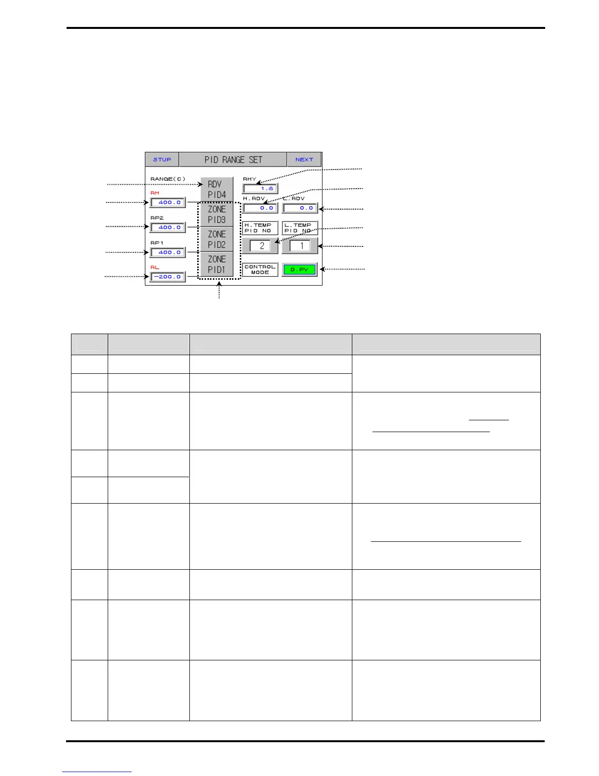
2.12.4 PID SET SCREEN
2.12.4.1 PID RANGE SET
▶ Consists of 3 Temperature PIDs and 1 deviation PID.
Diagram 2-52. PID Range Set Screen
No. Instruction Contents Additional Explanation
○
1
RDV PID Deviation PID
○
2
ZONE PID Temperature PID group.
▶ Shifts to the setting screen of target
▶ PID group if you press number.
○
3
TEMP RANGE
HIGH
High limit of temperature.
▶ It changes as TEMP.RH(TEMP RANGE
▶ HIGH) setting point of 2.12.1.1
▶ Temperature Input Setting
changes.
☞ Cannot amend.
○
4
REFERENCE
POINT2
○
5
REFERENCE
POINT1
Sets limit value which selects
ZONE PID for temperature SPAN.
▶ RL≤RP1≤RP2≤RH
○
6
TEMP RANGE
LOW.
Low limit of temperature.
▶ It changes as TEMP.RL ▶ (TEMP
▶ RANGE LOW) setting point of
▶ 2.12.1.1 Temperature Input Setting
▶ changes.
☞ Cannot amend.
○
7
REFERENCE
HYSTERESIS
Selects ysteresis width when
selecting PID group at Zone PID.
○
8
High
Temperature
Room
REFERENCE
DEVIATION
Sets deviation value when
choosing high temperature PID.
○
9
Low
Temperature
Room
REFERENCE
DEVIATION
Sets deviation value when
choosing low temperature PID.
○
7
○
9
○
11
○
12
○
2
○
1
○
3
○
4
○
5
○
6
○
8
○
10