51
For your convenience, PAS shows the deadbands both in percent and in engineering
units, and also indicates the minimum and maximum process measurements from which
the percent deadband is taken.
2. Adjust the default percent deadbands to the desired values as required for your
application. The allowable range is 0.001% to 50.000%. Press Enter or click with the left
mouse button elsewhere on the dialog window to update the engineering deadbands.
3. Send your setup to the device.
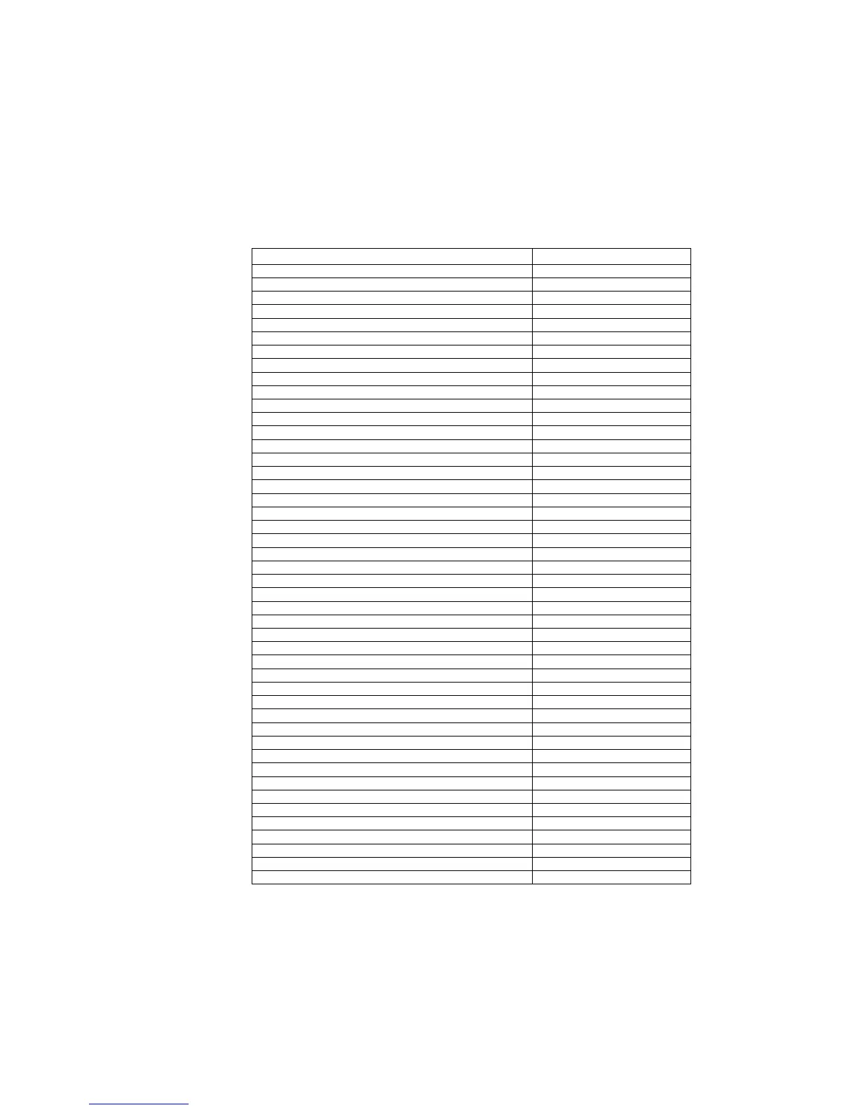
The following table shows the default factory-set deadbands for all measured analog values.
Measured Value Default Deadband, %
Phase voltage 1.000
Auxiliary voltage V4 1.000
Phase currents 1.000
Neutral current 1.000
Auxiliary current I4 1.000
Phase currents (extended inputs) 0.133
Neutral current (extended inputs) 0.133
Auxiliary current I4 (extended inputs) 0.133
Voltage sequence 1.000
Current sequence 1.000
Current sequence (extended inputs) 0.133
Voltage unbalance 0.333
Current unbalance 0.333
Active power 0.500
Reactive power 0.500
Active power import/export 1.000
Reactive power import/export 1.000
Apparent power 1.000
Active power demand 1.000
Reactive power demand 1.000
Apparent power demand 1.000
Power factor 5.000
Power factor lag/lead 10.000
Frequency 0.100
Voltage THD 0.100
Current THD 0.500
Voltage interharmonic THD 0.100
Current interharmonic THD 0.500
Current TDD 1.000
Current K-factor 0.100
Analog input #1 1.000
Analog input #2 1.000
Analog input #3 1.000
Analog input #4 1.000
Analog input #5 1.000
Analog input #6 1.000
Analog input #7 1.000
Analog input #8 1.000
Analog input #9 1.000
Analog input #10 1.000
Analog input #11 1.000
Analog input #12 1.000
Analog input #13 1.000
Analog input #14 1.000
Analog input #15 1.000
Analog input #16 1.000
6.8 Generating a CID File
Generating a new or updating a preconfigured CID file for your device is done
separately for each configuration setup. The following order is recommended but
not mandatory: