Technical Specifications Appendix D Cable Drawings - Computer Connection
153
Appendix D Cable Drawings - Computer
Connection
RS-232 Cable Connections
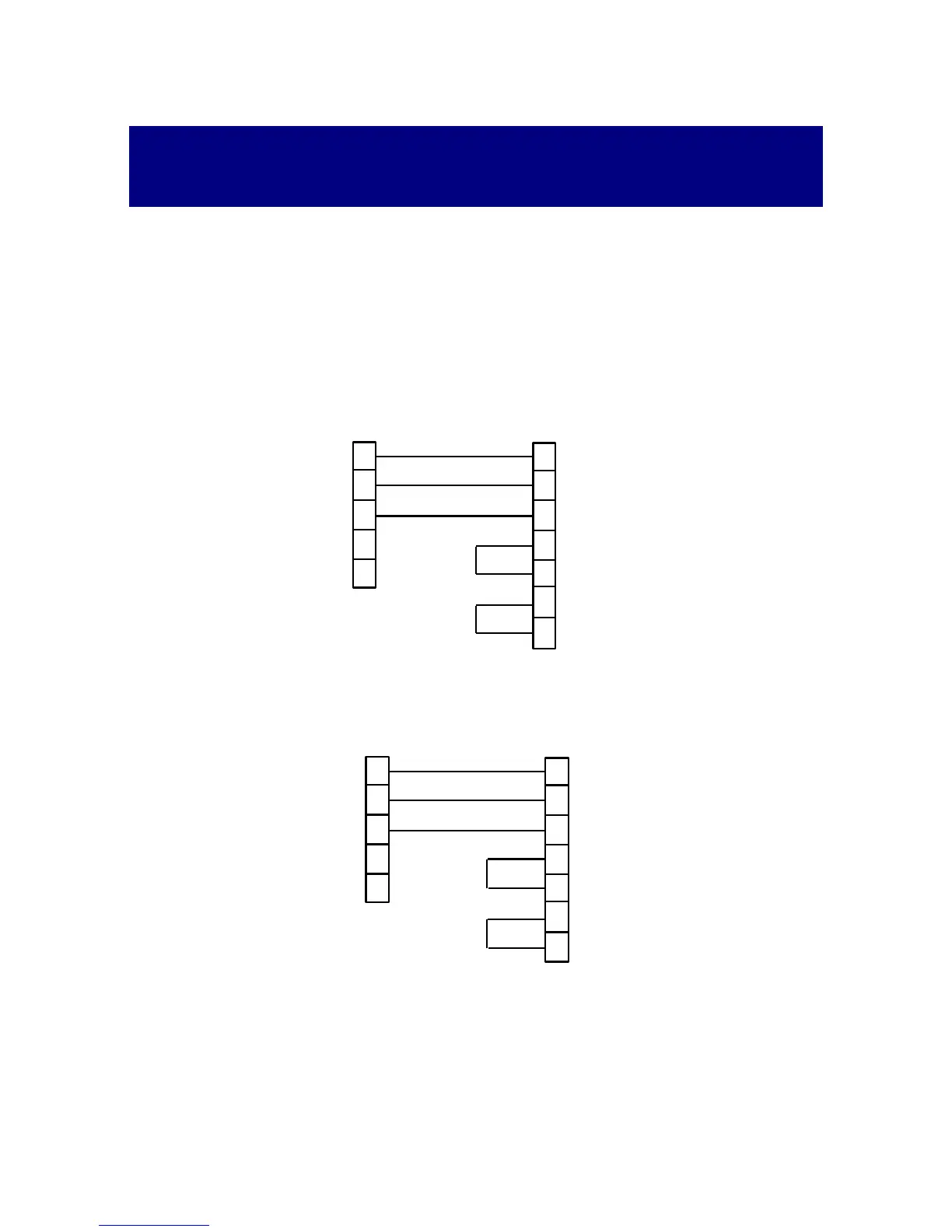
Simple 3-wire Connection
Set the handshaking mode and DTR/RTS control line to NONE (see Section
3.3.8). At the PC cable end, make a short between DSR & DTR pins, and between
RTS & CTS pins.
25-pin Computer Connector
9-pin DB9 male connector 25-pin DB25 female connector
1
2
3
Powermeter
TxD
RxD
RxD
TxD
7
3
2
6
5
5
4
20
DSR
CTS
GND
GND
IBM PC/Compatible
4
RTS
DTR
DSR/CTS
DTR/RTS
9-pin Computer Connector
9-pin DB9 male connector 9-pin DB25 female connector
1
2
3
Powermeter
TxD
RxD
RxD
TxD
3
2
6
5
5
4
DSR
CTS
GND
GND
4
8
IBM PC/Compatible
RTS
DTR
7
DSR/CTS
DTR/RTS