EasyManuals Logo

Satec System 295 User Manual

Default Icon
173 pages
To Next Page IconTo Next Page
To Previous Page IconTo Previous Page
Page #171 background imageLoading...
Page #171 background image
Appendix F Cable Drawings - Modem Connection 163
Appendix F Cable Drawings - Modem
Connection
Set the handshaking mode to NONE, and communications mode to tELE mode.
Configure the remote modem to answer incoming calls automatically and ignore
the DTR signal; disable the flow control option. Refer to your modem manual for
appropriate commands. In most cases, you can use the following command string
to set up your remote modem:
ATS0=1&D0&K0&W0
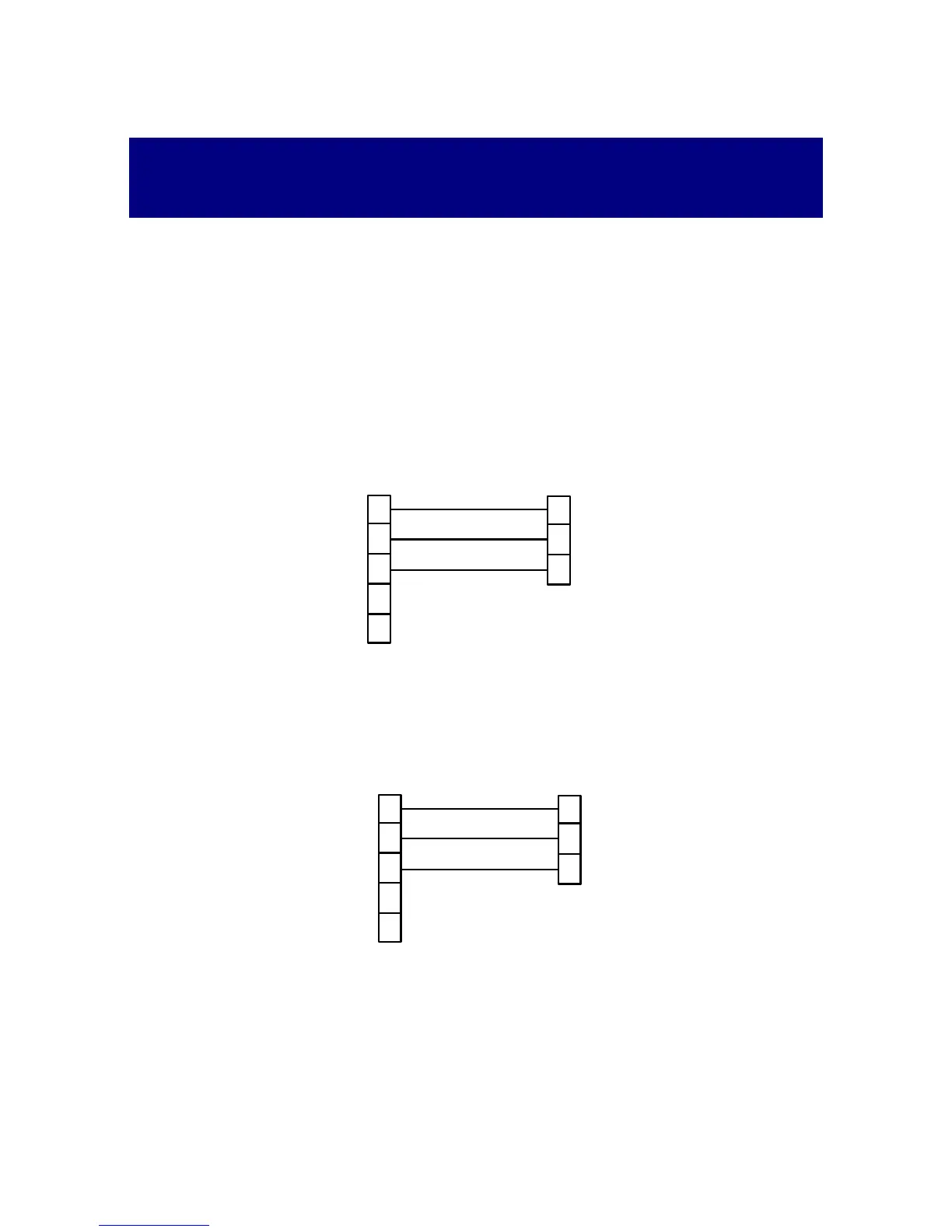
25-pin Modem Connector
1
2
3
Powermeter
TxD
RxD
RxD
TxD
7
3
2
5
4
DTR/RTS
GND
GND
A 9-pin DB9 male connector
A 25-pin DB25 male connector
Modem
DSR/CTS
9-pin Modem Connector
1
2
3
Powermeter
TxD
RxD
RxD
TxD
3
2
5
4
DTR/RTS
GND
GND
A 9-pin DB9 male connector
5
Modem
DSR/CTS

Table of Contents

Questions and Answers:

Question and Answer IconNeed help?

Do you have a question about the Satec System 295 and is the answer not in the manual?

Satec System 295 Specifications

General IconGeneral
BrandSatec
ModelSystem 295
CategoryMeasuring Instruments
LanguageEnglish

Related product manuals