Installation 27
2.11 Relay Output Connections
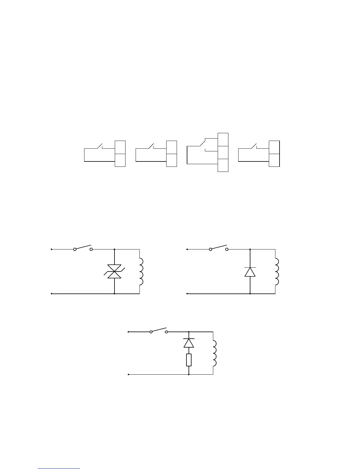
The PM295 is equipped with four electromechanical relays. Relays #1, #2, and #4
are two-contact Form A (SPST) relays, and relay #3 is a three-contact Form C
(SPDT) relay. Relay #1 is a reed relay that is intended for a small load, for example,
to output pulses. For the relay ratings, see technical specifications in Chapter 6.
Figure 2-15 illustrates wiring connections for the relays.
All relays are normally de-energized.
19
23
25
27
Figure 2-15 Relay Output Connections
Relay Contact Protection
When using relay outputs for switching lamp, capacitive or inductive circuits, some
form of transient suppression may be necessary to keep the relay contacts within the
voltage or current ratings. The following diagrams recommend some variants of
protective circuits for relay outputs.
LOADV s
Figure 2-16 Inductive load - Zener Diode
Protection
LOADsV
Figure 2-17 Inductive load - Diode Protection
LOADsV
+
-
Figure 2-18 Inductive Load - Diode/resistor Protection