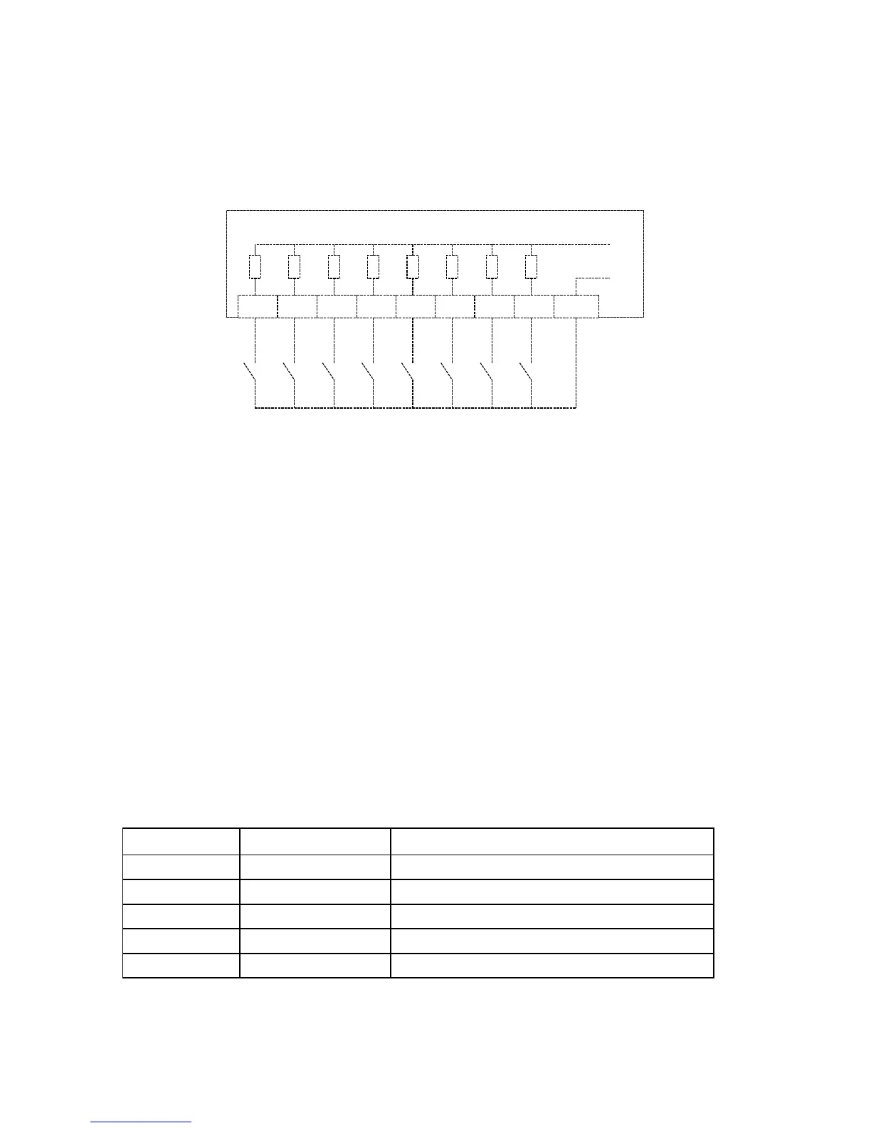
2.12 Discrete Input Connections
The PM295 provides eight optically isolated dry-contact sensing (voltage-free)
discrete inputs. Figure 2-19 shows wiring for discrete inputs.
K1 K2 K3 K4 K5 K6 K7 K8 COM
6 8 1210 14 16 18 20 11
+5 V
0 V
1 kOhm
PM295
Figure 2-19 Discrete Input Connections
The dry contacts connected to discrete inputs must be floating relative to the ground
with a minimum rating of 5 VDC, 5 mA. It is also recommended to perform
connections using a shielded, twisted pair cable that is isolated from noise sources.
2.13 Communications
Connector Pinout
The communications port is optically isolated and supports both EIA RS-232 and
RS-422/485 standard interfaces (user-selectable). The serial interface connector is
standard D-type 9 pin female plug-in, located at the top center of the back of the
instrument. Tables 2-1 and 2-2 list the pinout of the connector.
NOTE
The functions of pins 4 and 5 can be programmed via keypad upon the needs of the user.
Refer to Section 5.3 on how to select the appropriate pin function.
Table 2-1 RS-232 pinout
Pin Name Function
1 0V Common
2 TXD Transmit Data
3 RXD Receive Data
4 DTR/RTS Data Terminal Ready/Request to Send
5 DSR/CTS Data Set Ready/Clear to Send