97-04023
31
2 5 8
4
1011
6 7
12
9
+ -
L
N
+
K
LOAD
-
L3 (C)
L2 (B)
L1 (A)
11
1
2
3
5 8
4 6
N
L1 (A)
L2 (B)
L3 (C)
10
7 9
+
12
-
+ -
LOAD
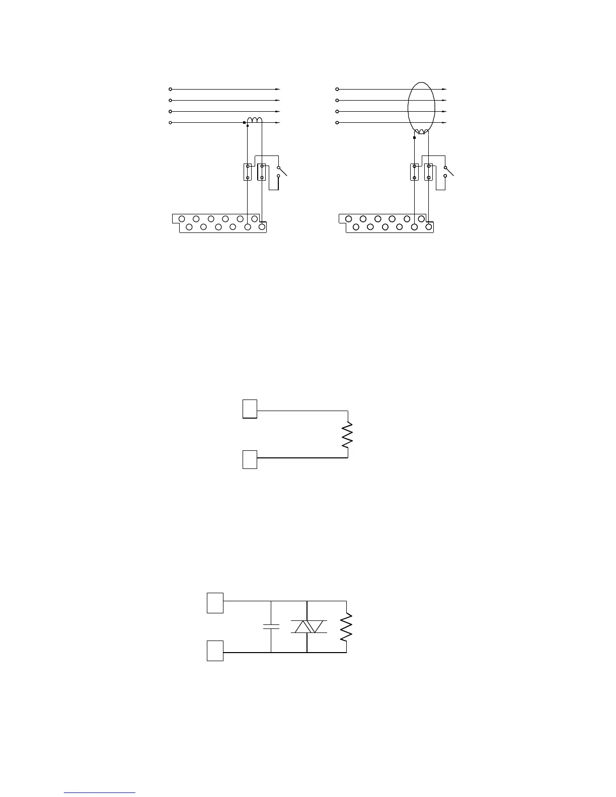
a) Neutral current b) Ground leakage current
Figure 2-12 Auxiliary Current Input Connections
2.10 Analog Output Connections
Figure 2-13 shows wiring for an analog output. The analog output is optically
isolated and has an internal source +24 VDC to power the current loop. Analog
output range is 0-20 or 4-20 mA, as per your order.
R
L
max 510 Ohm
15
13
+
-
Figure 2-13 Analog Output Connections
The permitted range for the current loop resistance is 0 to 510 Ω.
In many industrial applications, it may be necessary to protect the output from
accidental shorts to AC line voltages, in addition to high common-mode voltages.
The circuit shown in Figure 2-14 can be used for this purpose.
R
C1
L
VR1 = 25 VRMS
VR1
13
15
C1 = 0.1 mF/50V