Appendix E Cable Drawings - Printer Connection 159
Appendix E Cable Drawings - Serial
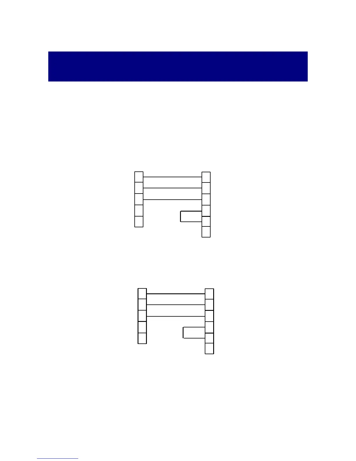
Printer Connection
Simple 3-wire Connection
Set the handshaking mode and the DTR/RTS control line to NONE (see Section
3.3.8). Do not use this connection if your printer has less than 256 bytes of input
buffer.
At the printer's cable end, make a short between DSR and DTR pins.
25-pin DTE Printer Connector
1
2
3
Powermeter Printer
TxD
RxD
RxD
TxD
7
3
2
6
5
5
4
20
DSR
DTR
CTS
GND
GND
A 9-pin DB9 male connector A 25-pin DB25 female connector
DSR/CTS
DTR/RTS
9-pin DTE Printer Connector
1
2
3
Powermeter Printer
TxD
RxD
RxD
TxD
3
2
6
5
5
4
DSR
DTR
CTS
GND
GND
A 9-pin DB9 male connector A 9-pin DB9 female connector
4
8
DSR/CTS
DTR/RTS