160 Appendix E Cable Drawings - Printer Connection
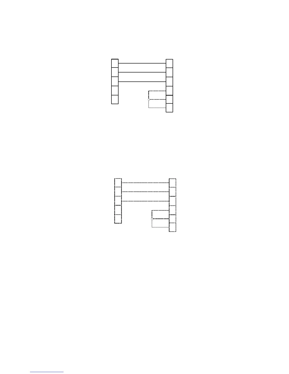
25-pin DCE Printer Connector
1
2
3
Powermeter Printer
TxD
RxD
RxD
TxD
7
3
2
5
4
20
DTR
GND
GND
A 9-pin DB9 male connector A 25-pin DB25 male connector
RTS
4
DSR
6
DSR/CTS
DTR/RTS
In some printers, an additional short may be needed between DSR and RTS pins
(dashed line).
9-pin DCE Printer Connector
1
2
3
Powermeter Printer
TxD
RxD
RxD
TxD
7
3
2
5
4
DTR
GND
GND
A 9-pin DB9 male connector
RTS
4
DSR
6
A 9-pin DB9 male connector
5
DSR/CTS
DTR/RTS
In some printers, an additional short may be needed between DSR and RTS pins
(dashed line).