lower window displays the value for the selected parameter. See Section 4.10 for
information on analog output operation.
An 1
GrP
nonE
To select an analog channel setup:
Ä From the upper window, select the desired channel with the
up/down arrow keys.
To view the analog channel parameters:
Ä Press SELECT to choose the central window.
Ä Scroll through the list of parameters with the up/down
arrow keys.
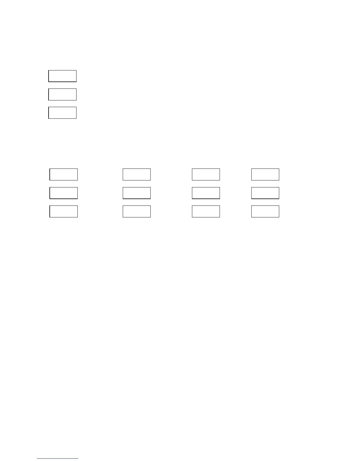
The following illustrations show what the parameter windows look like:
An 1
GrP
rt.Ph
Output
parameter
group
An 1
Out
U 1
Output
parame-
ter name
An 1
Lo
0
Zero
(low)
scale
An 1
Hi
660
Full
(high)
scale
All measured parameters that can be assigned to the analog output channel are
organized in groups listed in Table B-4a (see Appendix B) with the corresponding
group label. The analog output parameter is defined by both the parameter group
and parameter name within the group. All applicable parameters are listed in Table
B-4b with their default zero and full scales.
NOTE
When the analog scale value exceeds the number of places in the window, the
high order digits are expanded to the left window giving a resolution up to 7 digits.
If the value still exceeds the maximum available resolution, it is converted to
higher units (for instance, kW to MW) and a decimal point is placed in the window
to indicate the new measurement range.
To assign the parameter to the analog output channel:
Ä In the central window, select the GrP entry with the up/down arrow keys.
Ä Press SELECT to move to the lower window.
Ä Scroll through the group labels with the up/down arrow keys until the desirable
entry appears.
Ä Press ENTER to return to the central window.