ERECTION AND DISMANTLING
30
V23C_09.13
SC4000 Pos 4
3. Lift the chassis by turning the drive
shafts equally so that the tyres do
not touch the ground. The air gap
be tween the tyres and the ground
is usually about 30 mm.
- level the chassis and a mast on ver-
tical position with the level in di cator,
use the wooden ground plates un-
der jacks.
- lock drive shafts
WARNING !
Drive shafts of
all jacks shall
be locked
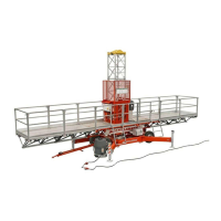
4. Screw the platform sections (the rail-
ings included) the symmetrically to
each other the with help of a spe cial
Drawing 4.25. Assembly of platform sections.
20-140295-1
LEVEL INDICATOR
30 mm
tool which has been designed for
plat form assembly. Use only screws
de liv ered by the manu fac turer.
Tighten the screws 195 Nm.
5.
Assemble the rst mast section.
Use only screws delivered by the
manu fac turer. Tighten the screws
350 Nm.
6.
Fasten the middle platform sections
to the right side mast basic section
viewed from the mast side of the
plat form (min. two pieces, max. nine
pieces) acc. to the needed total
length of the platform. While assem-
bling the middle platform re mem ber
to support the platform from the bot-
tom e.g. by using mast sections.
NOTE: THE RAILINGS SHALL ALSO BE
ASSEMBLED, SO THAT THE WHOLE
PLATFORM IS SURROUNDED BY RAI-
LINGS.
Drawing 4.24. Location of level indicator. Air gap 30 mm.
!
lock
 Loading...