Section10FUELSYSTEM
Subsection 01 (FUEL CIRCUIT)
Fuel System Pressurization
Proceed as follows:
– Fill up fuel tank (recommended but not manda-
tory).
– Install a hose pincher (P/N 295 000 076) on fuel
tank vent hose.
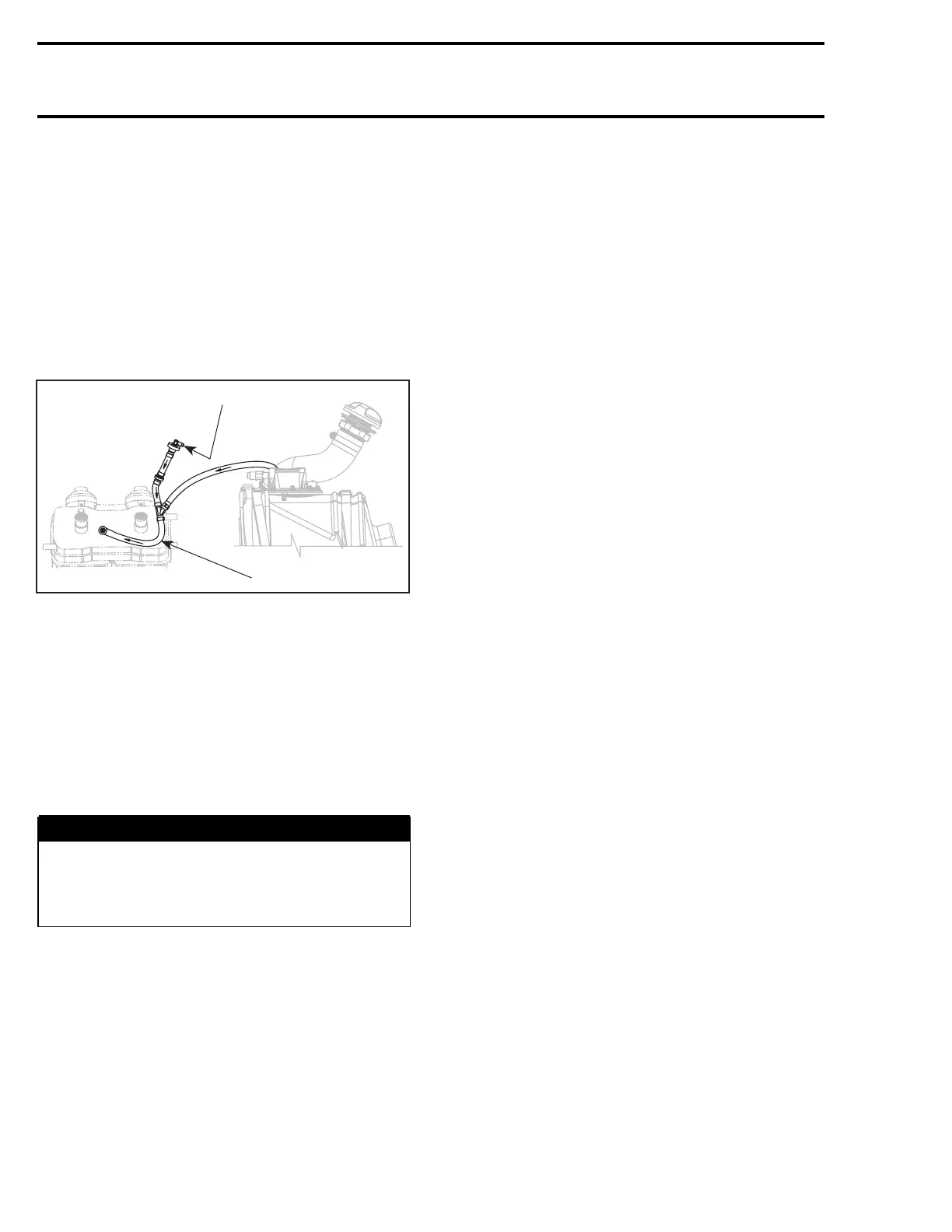
– Connect pump gauge tester (P/N 529 021 800)
to air inlet hose fitting.
NOTE: This pump is included in the ENGINE LEAK
TESTER KIT (P/N 295 500 352).
F22F01A
1
2
1. Connect pump to air inlet fitting
2. Install hose pincher on this hose
– Pressurize fuel system to 34 kPa (5 PSI).
– If pressure is not maintained locate leak and re-
pair/replace component leaking. To ease leak
search spray a solution of soapy water on com-
ponents, bubbles will indicate leak location.
NOTE: The system must maintain a pressure of
34 kPa (5 PSI) during 10 minutes. Never pressur-
izeover34kPa(5PSI).
WARNING
If any leak is found, do not start the engine
and wipe off any fuel leakage. Do not use
electric powered tools on watercraft unless
system has passed pressure test.
Remove hose pincher from fuel tank vent hose.
Make sure pressure is dropping on pump gauge
tester.
NOTE: Pressure drop indicates that relief valve
and the outlet fitting are not blocked.
Remove the pump gauge tester from the air inlet
hose fitting.
High Pressure Test (fuel pump circuit)
Install safety lanyard on DESS post to activate fuel
pump. Check for any leakage at fuel rail, injectors
and fuel hose.
32 smr2004-3D
 Loading...