Section 12 ELECTRICAL SYSTEM
Subsection 04 (INSTRUMENTS AND ACCESSORIES)
INSTRUMENTS AND ACCESSORIES
GENERAL
Install safety lanyard to activate MPEM and VCM
to perform testing procedures that requires the
device to be supplied with electricity.
VEHICLE CONTROL MODULE
(VCM)
The VCM is directly powered by the battery
through the 20A main fuse.
The following electrical system functions are con-
trolled by the VCM:
– power supply cut-off
– indicator light cluster
– electric bilge pump
– off-throttle assisted steering (OTAS)
Power Supply Cut-Off
When the safety lanyard is on its switch, the VCM
internal relay allows current to be supplied from
the battery to the RED/PURPLE wire which sup-
plies the MPEM and its dependent components.
Simultaneously, the VCM supplies its own depen-
dent components. Refer to WIRING DIAGRAMS
section.
When the safety lanyard is NOT on its switch, the
internal relay cuts the current supply from the bat-
tery and thus prevents current drain that would
slowly discharge the battery.
Test the signal wire to the power supply cut-off
relay as follows:
Disconnect DESS switch wires.
Connect test probes to switch BLACK and BLACK/
PURPLE wires.
With safety lanyard NOT on its switch: Mea-
sure resistance. There should be NO continuity
(open circuit). Otherwise replace DESS switch.
With safety lanyard INSTALLED on its switch:
Measure resistance. There should be continuity.
Otherwise replace DESS switch.
Reconnect DESS connector.
If switch tests good in both checks, do the follow-
ing.
Disconnect the AMP connector #3 from MPEM.
Using a voltmeter, perform the following test:
Connect one test probe to the harness connector
atpin 26 and the other probe to the battery ground.
Reading should be 0 V when safety lanyard is re-
moved. Otherwise, replace the VCM.
Keeping the test probes at the same position, in-
stall safety lanyard to DESS post. Measure volt-
age. Reading should be above 10 V. Otherwise,
check wiring and if it is good, replace the VCM.
If there is no current supply to the electrical com-
ponents while the DESS switch and the VCM test
good, check the wiring harness going to the com-
ponent and the component itself. If it tests good,
the MPEM could be suspected. Try a new one.
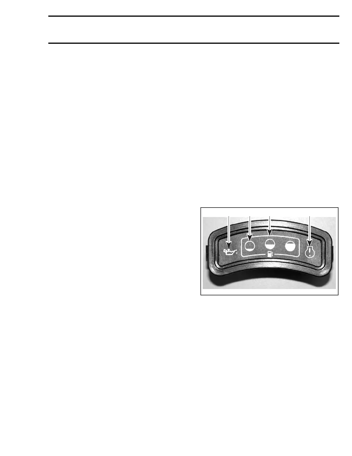
Indicator Light Cluster
F22H01A
1 3 2 4
1. Low oil warning light
2. Fuel level lights
3. Low fuel level light
4. Warning light
NOTE: When safety lanyard is installed, the fuel
pump will be activated for 1 second to build up
pressure in the fuel injection system.
The low oil warning light will turn on whenever oil
level is low in reservoir.
CAUTION: Always replenish oil reservoir as
soon as possible to avoid serious engine dam-
age.
When safety lanyard is installed and fuel tank is
full, all lights are continuously turned on. As fuel
level goes down, the fuel level lights will turn off
one at a time to indicate remaining fuel.
smr2004-3D 41
 Loading...