Section 14 STEERING SYSTEM
Subsection 01 (STEERING SYSTEM)
ASSEMBLY
Assembly is essentially the reverse of disassem-
bly procedures. However, pay particular attention
to the following.
CAUTION: Apply all specified torques and ser-
vice products as per main illustration at the be-
ginning of this subsection.
Steering Pole
NOTE: It is suggested to hook-up steering pole to
the ceiling to hold it while installing to vehicle and
particularly while installing steering cable.
Routesteeringcabletowardjetpumpmakingsure
to route along bilge.
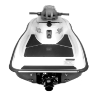
Maintain steering pole vertically while inserting
steering cable in pole.
Insert spring end into bridge mount hole.
F22K1QA
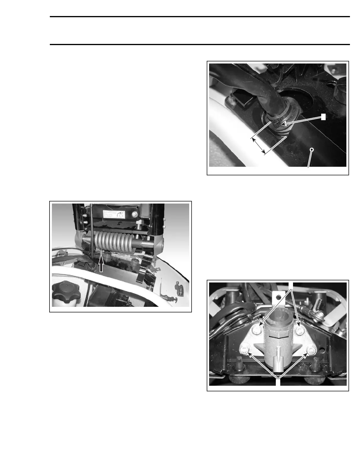
Secure pole to bridge mount. Torque nuts in a
criss-cross sequence.
Ensure to center pivot tube no. 35 with clamps
no. 36.
Insert wiring harness and throttle cable in pole.
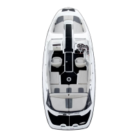
Ensure to stretch boot in the bridge mount no. 34
to the indicated length. Then install a locking tie
and strongly tighten.
NOTE: Ensure steering pole is centered (refer-
ence fuel tank cap).
1
F22K1RA
2
A
1. Bridge mount
2. Tightened locking tie
A. 45 mm (1.77 in)
NOTE: A missing or unfastened locking tie would
allow water entry in bilge.
Steering Stem and Support
Position steering support no. 23 onto steering
pole.
Lubricate moving parts and bushings.
Position washers no. 37 against top nuts.
Install steering pole retainer no. 46 on bottom
screws.
F22K1SA
1
2
1. Washers against nuts here
2. Steering pole retainer against nuts here
Torque screws no. 24 of steering support in a
criss-cross sequence.
smr2004-3D 73
 Loading...