Section 12 ELECTRICAL SYSTEM
Subsection 04 (INSTRUMENTS AND ACCESSORIES)
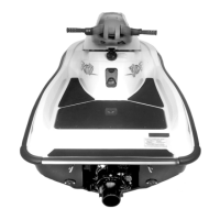
NOTE: In BUDS, position and hold the mouse
pointer over the needle of the throttle opening to
get the actual value.
F22H0HA
Value= 17.3%
MIN=
MAX=
Throttle Opening
THROTTLE OPENING GAUGE IN BUDS
Alternately, the MPEM Programmer can be used.
Adjust throttle opening to get a value of 18.4° +/-1.
If none of these tools are available, resistance can
bemeasuredwithanohmmeteronwiresgoingto
the TPS.
Disconnect the AMP connector #4 from the
MPEM.
Measure and note resistance between pins 4 and
11 of TPS wiring while at the idle position.
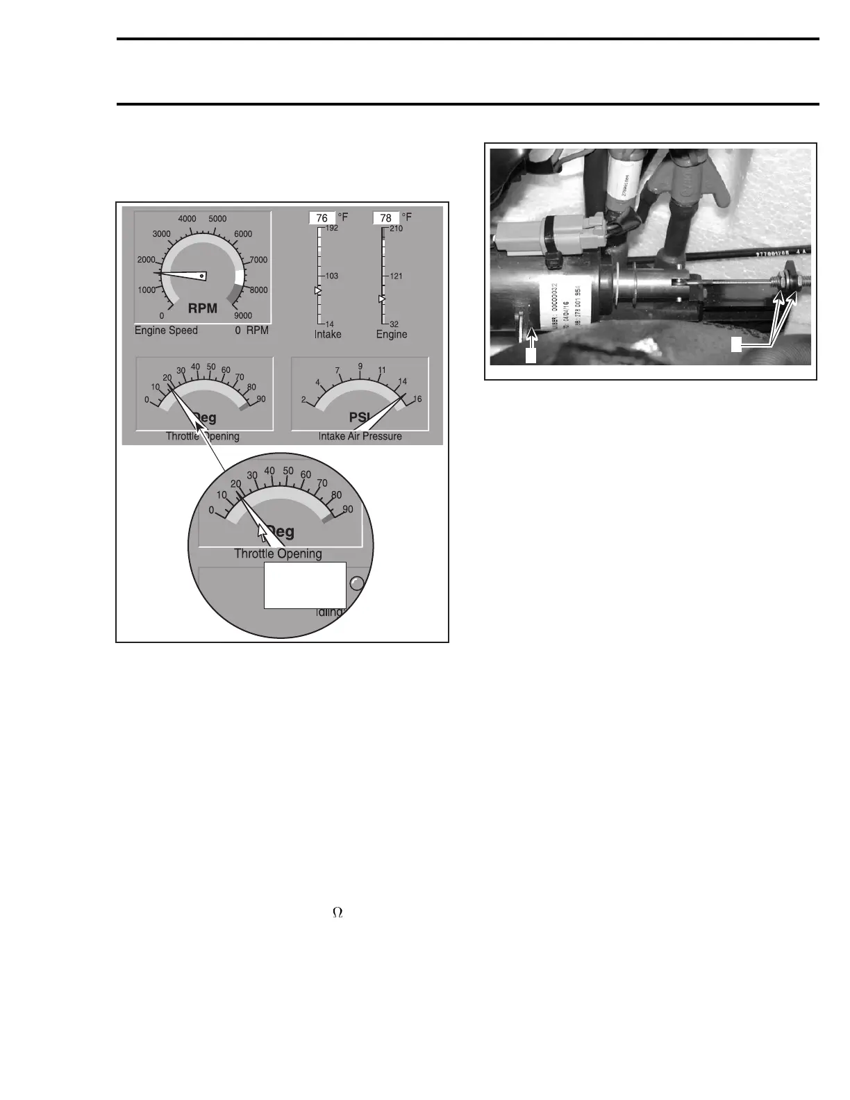
Push in solenoid rod and HOLD. Measure resis-
tance again.
Adjust cable at solenoid bracket to get an in-
creased resistance value of 165
.
F22H0BB
2
1
1. OTAS solenoid
2. Adjust here
MULTI-PURPOSE ELECTRONIC
MODULE (MPEM)
The MPEM is powered by the battery through the
VCM. It has a micro-processor inside of its sealed
case.
Most of the electrical system is controlled by the
MPEM. It is in charge of the following electrical
functions:
– interpreting information
– distributing information
– start/stop function
– Digitally Encoded Security System
– ignition timing curve
– engine rev limiter.
Some fuses are directly mounted onto the MPEM.
The MPEM features a permanent memory that
will keep the programmed safety lanyard(s) active
and other vehicle information, even when the bat-
tery is removed from the watercraft.
MPEM Functions
Safety Lanyard Reminder
If engine is not started within 5 seconds after
installing the safety lanyard on its post, 4 short
beeps every 3 second interval will sound for ap-
proximately 2 hours to remind you to start the en-
gine or to remove safety lanyard. Afterwards, the
beeps will stop. The same will occur when safety
lanyard is left on its post 5 seconds after engine is
stopped.
smr2004-3D 45
 Loading...