Section12ELECTRICALSYSTEM
Subsection 04 (INSTRUMENTS AND ACCESSORIES)
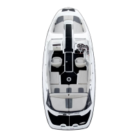
Disconnect the switch 4-pin connector.
F22H0DA
1
1. 4-pin connector
Perform the following tests for left and right sides.
Using an ohmmeter, probe the BLACK/WHITE and
BLACK wires of switch while steering is roughly at
its center position.
Resistance should be 470
. Otherwise, check
wiring harness and if good, replace switch.
Turn steering until it is blocked by its stopper.
Keep steering in this position.
Resistance should be 82 .
Otherwise, try any magnet and bring it in front
of the switch. If resistance is now good, replace
magnet.
If both resistance tests are good, check wiring har-
ness and if good, try a new VCM.
Reinstall steering pole cover.
O.T.A.S. Throttle Cable Adjustment
WARNING
Whenever solenoid or throttle cable has been
replaced, ensure to perform the O.T.A.S throt-
tle cable adjustment. Strictly follow the de-
scribed procedure.
The procedure consists of manually pushing the
solenoidrod(whichpullsthethrottlecableand
activates the throttle plate) while reading the TPS
opening or resistance value depending on the tool
used.
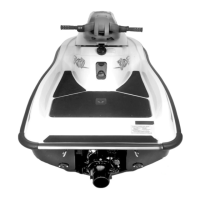
Fully push the solenoid rod in and HOLD (simulat-
ing the electrical activation) while reading the val-
ue.
F22H0AA
1
1. Push and HOLD solenoid rod
Use BUDS with the VCK and look in Throttle Open-
ing under Monitoring tab. Adjust cable at solenoid
bracket to get a value of 17.3% +/-1
44 smr2004-3D
 Loading...