15
Mechanical Installation
Remove the door (also disconnect the ground strap), the dead front and semi-flush mount the
backbox into the wall. Peel the adhesive cover from the trim ring and stick to the wall surface
around the backbox, after wall is finished.
4.2 Installing the Adder Modules
The MR-2320 Series panel comes pre-assembled with all components and boards except for
adder modules. Module installation locations are shown below. Refer to Figure 2 on the next
page for Jumper or DIP Switch settings and see Wiring Tables and Information on page 30 for
wiring specifications.
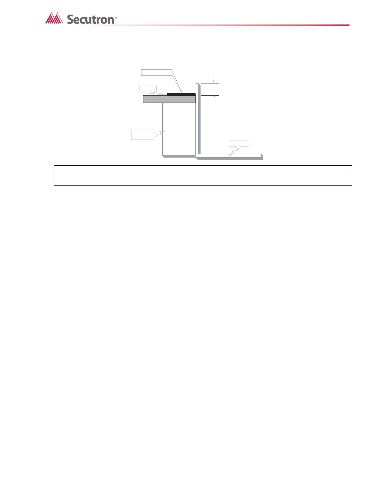
The figure below shows a cross-section of the semi-flush mounted backbox and the trim ring. Make sure
to allow a minimum depth of 1” above the wall surface for proper door opening.
TRIM RING
MIN 1”
WALL
WOOD OR
METAL STUD
BACKBOX

 Loading...


