23
Field Wiring
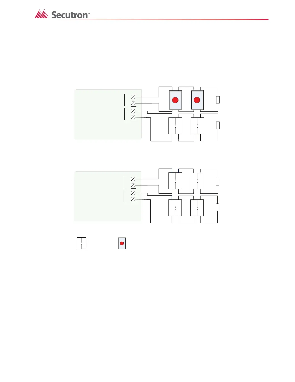
6.2 Abort and Manual Release Switch Wiring
Wiring for the abort and manual release switches is shown in Figures 10 and 11. The Abort
and Manual release switches must be on different circuits. DET5 is used for the Abort switch
and DET6 is used for the manual release switch.
Figure 10 Abort and Manual Release Switch Class B or Style B Wiring
FIRE ALARM MAIN BOARD
+
-
+
-
DET 5DET 6
INITIATING
CIRCUIT #5
INITIATING
CIRCUIT #6
3.9K 1/2 WATT ELR
OR ELRX-300/R
3.9K 1/2 WATT ELR
OR ELRX-300/R
MANUAL RELEASE
SWIT C H
Use MS-403 ,404
USE ONLY NO
CONTACT
ABORT SWITCH
CONNECT A UL /ULC LISTED ABORT STATION ACCEPTABLE TO
THE AHJ, COMPLYING WITH THE FOLLOWING SPECIFICATIONS:
MAXIMUM IMPEDANCE = 1.4K OHMS
RATED CURRENT = 45mA
RATED VOLTAGE= 24V
Manual Release switches on separate circuits
Abort and Manual Release switches on separate circuits
FIRE ALARM MAIN BOARD
+
-
+
-
DET 5DET 6
INITIATING
CIRCUIT #5
INITIATING
CIRCUIT #6
3.9K 1 /2 WATT ELR
OR ELRX-300/R
3.9K 1/2 WATT ELR
OR ELRX-300/R

 Loading...


