34
8.0 Indicators, Controls and Operations
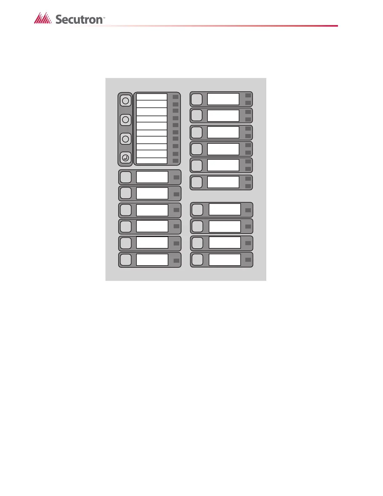
Refer to Figure 19 below for LED Indicator and Control Button locations.
Figure 19 LED indicators and control buttons
The Main Display Panel on the Main Pre-Action/Deluge and Agent Release Control Board
consists of:
• 16 common LED Indicators (left portion of display)
• Ten Common Buttons (left half portion of display)
• Up to six Initiating Circuit Alarm LEDs and six Initiating Circuit Trouble LED Indicators
• Four Indicating/Releasing Circuit LEDs (labeled NAC for Notifying Appliance Circuit or
RAC for Releasing Appliance Circuit)
• Up to ten disconnect buttons (six for initiating circuits & four for indicating/releasing
circuits)
LED Indicators may be amber, red, or green, and may illuminate continuously (steady), or at
one of two flash rates.
• Fast Flash (Supervisory)- 120 flashes per minute, 50% duty cycle
• Trouble Flash (Trouble) - 20 flashes per minute, 50% duty cycle
SYSTEM
RESET
AC ON
X
M
?
GROUND FAULT
CPU FAIL
ABORT
RELEASED
COMMON ALARM
COMMON SUPV
REMOTE TROUBLE
COMMON TROUBLE
BATTERY TROUBLE
SIGNAL
SILENCE
AUXILIARY
DISCONNECT
LAMP
TEST
PRE
RELEASE
RAC2
(ZONE 4)
RAC1
(ZONE 3)
NAC2
(ZONE 2)
NAC1
(ZONE 1)
IAC6
(ZONE 1)
IAC5
(ZONE 5)
IAC4
(ZONE 4)
IAC3
(ZONE 3)
IAC2
(ZONE 2)
IAC1
(ZONE 1)
ALM/SUP/TBL/
BLDG AUDIBLE SIL

 Loading...


