87
15.0 Appendix D: Power Supply and
Battery Calculations (Selection
Guide)
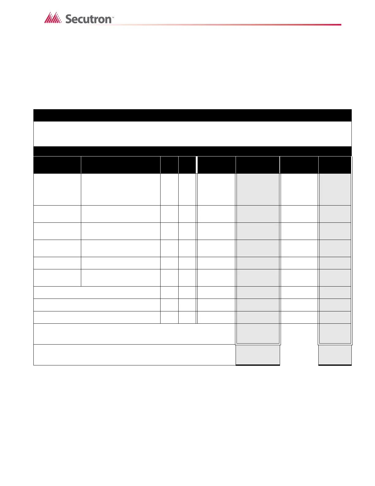
Use the form below to determine the required secondary power supply (batteries).
* Assume three Initiating Circuits are in alarm.
' Use 0.084 for five minutes, 0.168 for 10 minutes and 0.5 for 30 minutes of alarm as a multiplier figure.
Using the Mircom MPD-65P 2-wire photoelectric smoke detector. See LT-1007SEC Conventional Device Compatibility Guide for
other compatible smoke detectors.
Total Current Requirement: ALARM (B)______ Amps. (Value obtained from column B)
Battery Capacity Requirement:
Battery (AH) = ([STANDBY (A) ______ ] x [(24,60 or 90 Hours) ___ ]) +
([ALARM (B) ______ ] x [Alarm in Hr.] _____) = (C) ______AH
Total System Current in Alarm State: Must be 5.5 amperes or less for MR-2320 Series.
Battery Selection: Multiply (C) by 1.20 to derate battery.
IMPORTANT NOTICE
The main AC branch circuit connection for Fire Alarm Control Panel must provide a dedicated continuous power without provision of any
disconnect devices. Use #12 AWG wire with 600-volt insulation and proper over-current circuit protection that complies with the local codes.
Refer to Appendix C: Specifications on page 84 for specifications.
POWER REQUIREMENTS (ALL CURRENTS ARE IN AMPERES)
Model
Number
Description Qty Standby
Total
Standby
Alarm
Total
Alarm
MR-2320-R
Pre-Action/Deluge and
Agent Release Control
Panel FIXED ELR/ACTIVE
ELR
X 0.123/0.092
=
0.316/
0.292
=
MR-2300-A
Det Class A Converter
Adder Module
X0.000
= 0.000 =
MR-2300-NC2
Sig Class A Converter
Adder Module--2 Circuits
X0.000
= 0.000 =
MR-2300-PR
Polarity Reversal and City
Tie Module
X0.050
= 0.300 =
MR-2306-R6 6 Relay Adder Module X 0.000
= 0.080 =
MR-2312-S12
12 Relay Smart Relay
Module
X0.030
=0.140=
Two-Wire Smoke Detectors X 0.00011
= * 0.135 =
Four-Wire Smoke Detectors X
= =
Signal Load (bells, horns, strobes, and etc.) X
=
Auxiliary Power Supply for Annunciators, etc.
=
=
Total currents (Add above currents) STANDBY
(A)
ALARM
(B)

 Loading...


