4.13 Integrated Backup Phase Overcurrent Protection
The WIC1 has an additional integrated backup phase overcurrent protection (short: backup
protection). It is activated automatically if the WIC1 detects a device-internal (hardware
or software) error that still persists after several automatic restarts. This is not a typical
protection function, that can be activated or deactivated at any time, but it is a special
hardware-based operating mode of the WIC1. It guarantees some minimum protection
functionality in case of a permanent device-internal problem. In this operating mode,
there is only the backup phase overcurrent protection active, all other functionality is
switched o. The WIC1 indicates this by the “System Error” LED being continuosly lit up.
(See also ╚═▷ “4.13.1 Activation of the Backup Protection”, ╚═▷ “The »System« LED(s) –
“Ready”, “Error””.)
The backup protection operates independent of the rmware. Therefore no settings are
available, nor any kind of fault signaling (e.g. via SCADA or LEDs or fault recorder).
• The device variants WIC1‑xxxxxx1 (see ╚═▷ “2.6.1 Order Form of the Device”)•
output a trip pulse as soon as there is sucient electrical energy for this
(≲ 0.8⋅In,min).
•
For device variants WIC1‑xxxxxx2, the pickup threshold is approx. 20⋅In,max.
•
The trip pulse is given after a delay of approx. 40 ms.
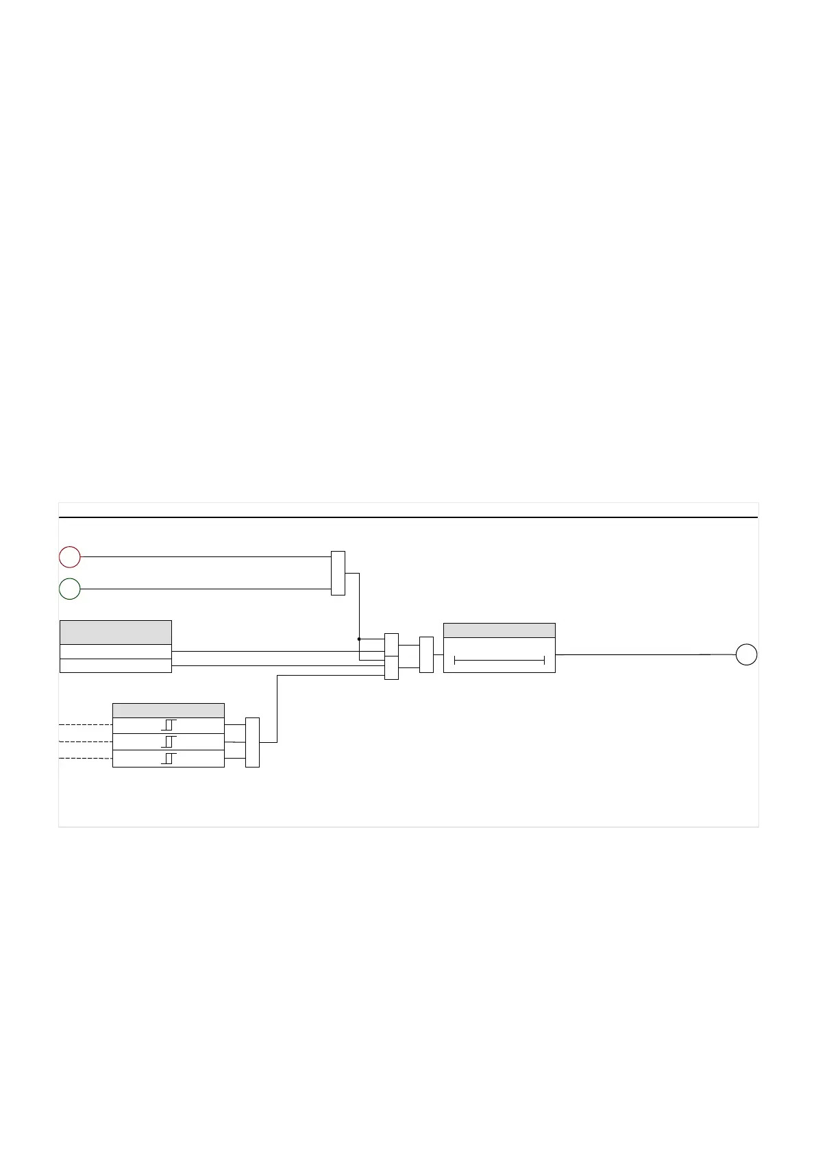
Backup Protection
wiBackupPOC_Y01
20 ⋅ In,max
IL1
IL2
IL3
≥1
40 ms
t
0
Hardware Option /
Device Variant
Directly
Threshold 20 In,max
&
&
≥1
53
Backup Protection . Trip command
4
“Error”
Please Refer To Diagram: wiProtGeneral_Y07
1
System . Prot. Ready
(Device has enough energy for trip pulse)
&
Fig. 64: Integrated Backup Phase Overcurrent Protection
174 WIC1 WIC1-1.0-EN-MAN
4 Protective Elements
4.13 Integrated Backup Phase Overcurrent Protection
 Loading...

