7.4 Measuring the Trip Delay
Variants of type WIC1‑xxxxC oer a freely congurable impulse output for a ag indicator.
(See ╚═▷ “3.7 Outputs (Trip Coil, Flag Indicator, Relay Output)” and the Order Options.)
Although this FI output has its primary use in triggering a ag indicator it can also be used for
special testing purposes if it is congurable; for example, it can be connected to the digital
input of a testing device. If the TC (trip coil impulse output) is then connected to another
digital input, then the testing device is able to measure the trip delay (i. e. the time-span
between pickup and trip).
Hardware
WIC1
WIC1_Z31
S1
S2
C
D
L1
Digital Inputs
N
1 A
1-phase∿
Testing Device
X3
X1
TC+
TC−
FI+
FI−
500 Ω
20 Ω
alternatively:
L1
Meas. Winding
Test Winding
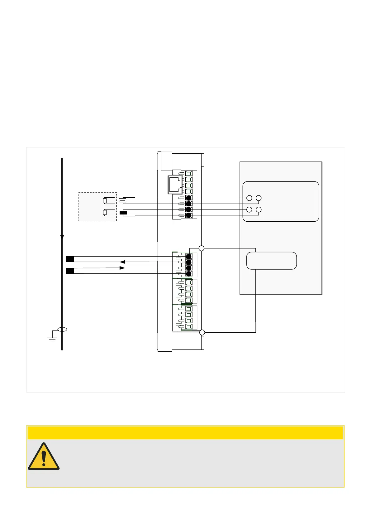
Fig. 70: Example of the connection of the digital inputs of a testing device (only phase L1 shown).
When connecting the impulse outputs for Trip Coil and Flag Indicator to the digital inputs of
the testing device, there are important rules to be followed:
CAUTION!
In the Hardware settings of the testing device, set up the digital inputs so that they
accept an input voltage between 17 V DC and 24 V DC as “binary 1”.
This means, in particular, that these digital inputs must not be dened as “potential-
free”.
201WIC1WIC1-1.0-EN-MAN
7 Commissioning
7.4 Measuring the Trip Delay
 Loading...

