9.2.2
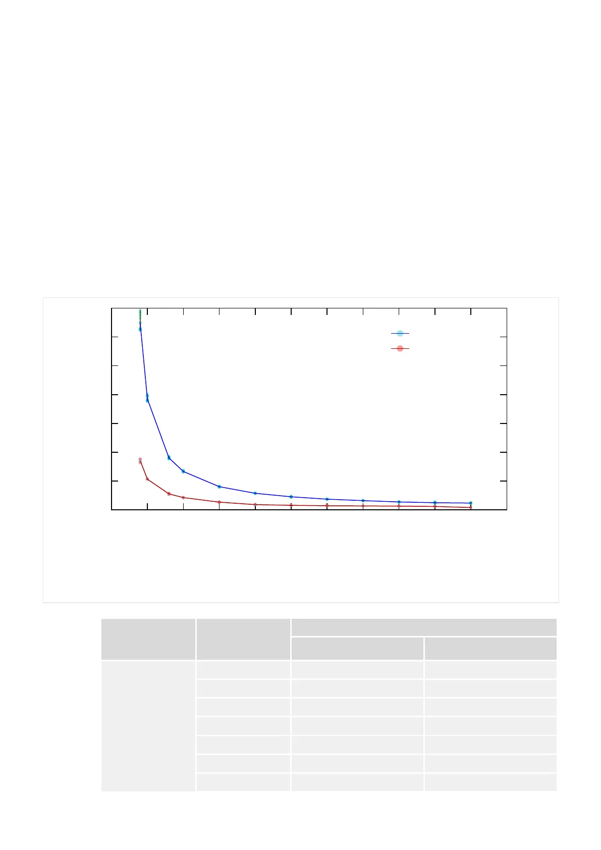
Measured Trip Times (fN = 50 Hz, 1‑/3‑phase)
Measurements for phase overcurrent:
• In = I
n,min
•
• Denite-time overcurrent (»Char« = “DEFT”).•
• Without additional trip delay (»I> . t« = 0).•
• Measured from power o until trip impulse signal.•
• Blue curve in the diagram below: 1 phase, 15 tests for each current value. Red•
curve: 3 phases, 5 tests for each current value.
• The setting »I« – labeled as I
>
. I in the diagram below – varies in the range•
0.5In … 2.5In.
Time To Trip [s]
Pickup I
>
.I = 0.35⋅In
WIC1_ZT5
I / In
0
0.2
0.4
0.6
0.8
1
1.2
1.4
0 0.5 1 1.5 2 2.5 3 3.5 4 4.5 5 5.5
1-phase
3-phase
Fig. 71:
Trip Times »I>«, measured from power o until trip impulse signal.
Pickup Setting I
[In]
I
[In]
Average Measured Trip Times [ms]
1-phase 3-phase
0.35 0.4 1295 342
0.5 770 213
0.8 360 111
1.0 267 85
1.5 161 54
2.0 115 37
2.5 90 32
221WIC1WIC1-1.0-EN-MAN
9 Technical Data
9.2.2 Measured Trip Times (fN = 50 Hz, 1‑/3‑phase)
 Loading...

