3.7 Outputs (Trip Coil, Flag Indicator, Relay Output)
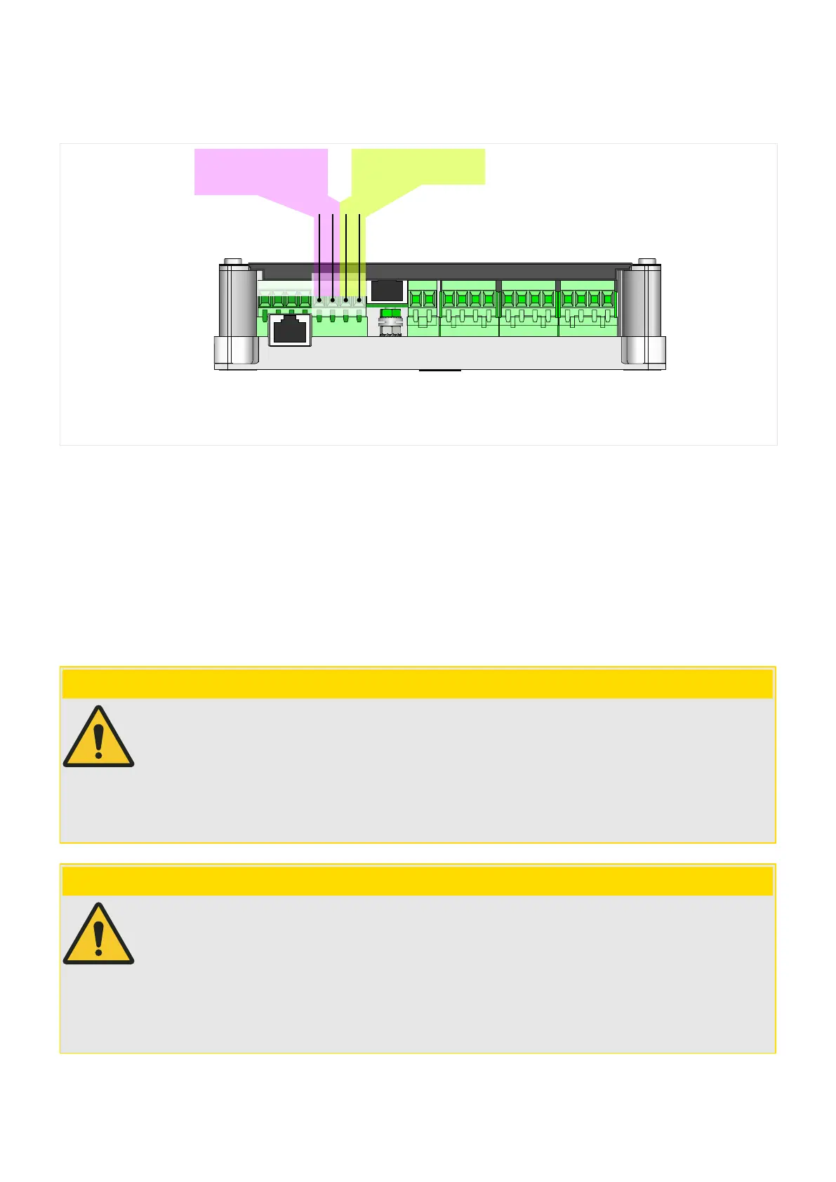
WIC1_Z12
X4
TC−
TC+
Output:
trip coil
Output:
Flag Indicator
FI−
FI+
or Relay Output
X4:
Tightening Torque: 0.5 Nm (4.4 lb⋅in)
Fig. 29: Terminal block X4: Outputs. Note that the WIC1‑4 has the outputs at X4‑5, X4‑6 labeled as
“Out+/−”, instead of “FI+/−”.
Terminal block X4 (see also ╚═▷ “3.1 Overview of Elements and Connectors”)
always features:
• a pulse output for a low-energy trip coil.•
Furthermore, it can feature (depending on the order options):
• an output, that operates as a pulse output for a mechanical ag indicator.•
For an externally supplied WIC1‑4, this output can also function as a relay output,
see ╚═▷ “Relay Output (WIC1‑4)”.
CAUTION!
It is not allowed to connect any active voltage to the trip coil output or to the output
(ag
indicator / relay output).
The two outputs may be connected at the same time to test equipment (e. g. to binary
inputs of an Omicron
©
device) only if these two binary inputs do not share a common
potential. Otherwise this external potential bridge, together with device-internal circuits,
can produce incorrect test results.
CAUTION!
For a WIC1‑4, it is also necessary that the
congured operating mode matches the
connected hardware!
(For example, it is not permissible to connect a ag indicator and set the operating mode
to “Syst. O.K. & Ext.Suppl.”. See also the related Self-Supervision warnings SW 3, SW 4.)
Moreover, the electrical energy that an output relay drains with operating mode “Syst.
O.K. & Ext.Suppl.” requires that the WIC1‑4 is supplied by an external auxiliary voltage.
86 WIC1 WIC1-1.0-EN-MAN
3 Hardware
3.7 Outputs (Trip Coil, Flag Indicator, Relay Output)
 Loading...

