5
Electrical installation
Assignment of the optional plug connectors
Operating Instructions – MOVIMOT
®
flexible
120
28126009
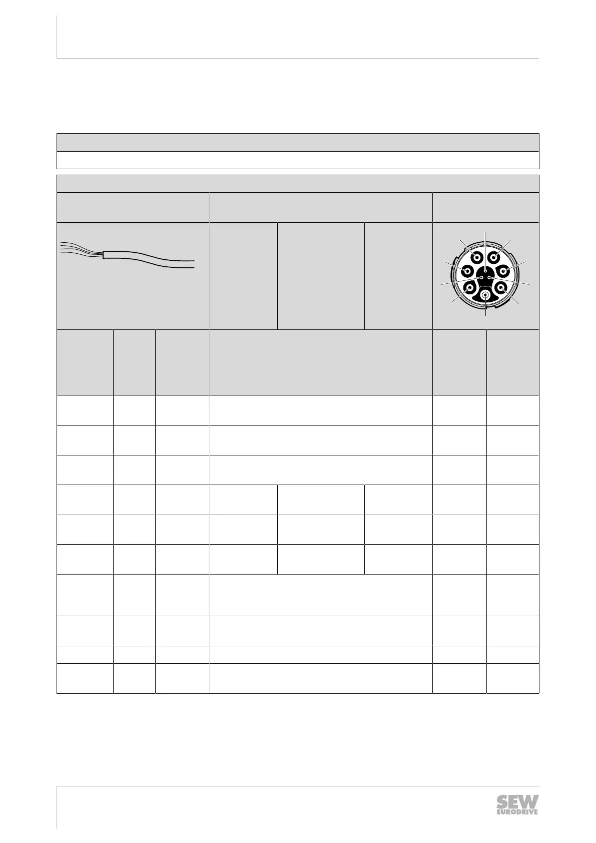
The following table shows the conductor assignment of cables with the following part
number:
Part numbers
281286009
Assembly
Open cable end,
conductor end sleeves
Motor connection depending on brake con-
trol
Prefabricated plug
connectors
Without
brake
3-wire brake
AC110–500V
(BE/BZ brake)
2-wire brake
DC24V
(BK/BP
brake)
Core
color/
Core
cross sec-
tion
Identi-
fication
Assembly Description Signal Contact
Black
1.5mm
2
U1
Conductor
end sleeve
Motor connection, phase U U A
Black
1.5mm
2
V2
Conductor
end sleeve
Motor connection, phase V V B
Black
1.5mm
2
W3
Conductor
end sleeve
Motor connection, phase W W C
Black
1.0mm
2
1
Conductor
end sleeve
Reserved
1)
Brake13 Brake+ Brake 13 D
Black
1.0mm
2
2
Conductor
end sleeve
Reserved
1)
Brake14 Reserved
1)
Brake 14 E
Black
1.0mm
2
3
Conductor
end sleeve
Reserved
1)
Brake15
Brake-
Brake 15 F
Green/yel-
low
1.5mm
2
–
Conductor
end sleeve PE connection PE PE
Black
0.75mm
2
4
Conductor
end sleeve
Connection temperature sensor+ Temp+ 1
– – – – Res. 2
Black
0.75mm
2
5
Conductor
end sleeve
Connection temperature sensor- Temp-
3
1) Reserved wires must be isolated and fixed in the connection box.
29129451/EN – 12/2019
 Loading...