AR-M550/M620/M700 SIMULATION 8 - 66
∗ Set DENA to 35. (Enter 35 as the adjustment value of DENA,
and press [P] key.) (0.1mm/step)
2) Make a copy at the normal ratio (100%) and check the lead edge
void area and the image loss. (Enter 100 as the set value of the
copy magnification ratio (MAGNIFICATION), and press [START}
key.)
3) If the adjustment result is not satisfactory, perform the following
procedures.
∗ If the lead edge void are is not 3.5mm:
Change the adjustment value of RRCB and perform the adjust-
ment. (Change the adjustment value of RRCB and press
[START] key.) (1msec/step)
∗ If the lead edge image loss is not 1.5mm:
Change the adjustment value of RRCA and perform the adjust-
ment. (Change the adjustment value of RRCA and press
[START] key.)
(Shift for the adjustment value change: 0.2mm/step)
(Rear edge void area adjustment)
Adjust so that the rear edge void area is 3.5mm. (Change the adjust-
ment value of TRAIL EDGE, and press [START] key.)
(Front/rear frame direction image loss adjustment)
Set the adjustment value of SIDE to 20. (Enter 20 as the adjustment
value of SIDE, and press [P] key.)
When the adjustment value is changed, the image position is shifted in
the front/rear frame direction.
(Front/rear frame direction void area adjustment)
Adjust so that the total of the front/rear direction void areas is 7.0mm.
(Change the adjustment values of FRONT/REAR, and press [START]
key.)
Front frame void area = 3.5mm Rear frame void area = 3.5mm
If, as shown above, the front and the rear void areas are not even, use
SIM 50-5 to adjust the image off-center position.
NOTE: When [P] is pressed after entering an adjustment value, the
adjustment value is set. When [START] key is pressed instead,
the adjustment value is set and copying is performed.)
(Copy condition in this simulation)
∗ To select paper (paper feed tray), perform the following procedures.
1) Enter 0 with 10-key.
2) Press [START] key. (The mode is changed to the paper feed tray
selection mode.)
3) Enter the number corresponding to the paper feed tray of the tar-
get paper with 10-key.
4) Press [START] key. (The paper feed tray is selected.)
∗ To set the magnification ratio, perform the following procedure.
1) Enter 2 with 10-key.
2) Press [START] key.
3) Enter the copy magnification ratio with 10-key.
4) Press [START] key.
Item Content
Set
range
Default
0 TRAY SELECT Paper feed tray selection 1 - 6 –
1 COPY START Copy START (Default) ––
2 MAGNIFICATION Print magnification ratio 25 -
400%
–
(Lead edge adjustment value)
3 RRCA Document scan start
position
0 - 99 50
4 RRCB Resist roller clutch ON
timing adjustment value
10 SIDE2 ADJ. Correction value for
RRCB in the back
surface print mode
1 - 99 50
(Image loss set value)
5 LEAD Lead edge image loss
set value
0 - 99 15
6 SIDE Side image loss set
value
20
(Void set value)
7 LEAD_EDGE
(DENA)
Lead edge void set value 0 - 99 35
8 TRAIL_EDGE
(DENB)
Rear edge void
adjustment value
9 FRONT/REAR Front/Rear void
adjustment value
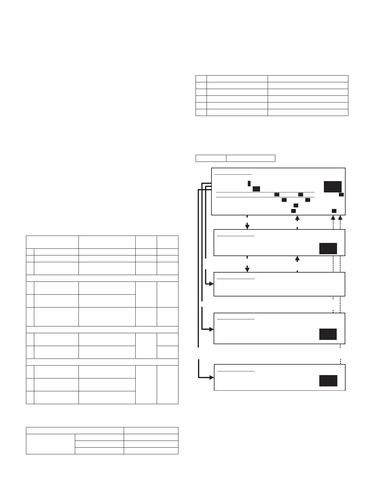
Normal display NOW COPYING.
ERROR display Door open DOOR OPEN.
Jam JAM
Paper empty PAPER EMPTY.
1TRAY1 TRAY1
2TRAY2 TRAY2
3TRAY3 TRAY3
4TRAY4 TRAY4
5 BPT Manual feed
6 LCC Side LCC
Set range 25 - 400 (%)
Select 2, and
press [START] key.
Press [START] key, or
press [CUSTOM SETTINGS] key.
50
1
2
Press [CUSTOM SETTINGS] key.
Press [START] key.
Press [CUSTOM SETTINGS] key,
or terminate copying.
Press [START] key or
press [CUSTOM SETTINGS] key.
SIMULATION 50-1
LEAD EDGE ADJUSTMENT. INPUT VALUE 0-99, AND PRESS
START.
3.RRCA
SIMULATION 50-1
LEAD EDGE ADJUSTMENT. NOW COPYING.
SIMULATION 50-1
LEAD EDGE ADJUSTMENT. SELECT 1-6, AND PRESS START.
(FEED TRAY)
1.TRAY1 2.TRAY2 3.TRAY3 4.TRAY4
5.BPT 6.LCC
Select 1, and
press [START] key.
Select 0, and press [START] key.
Select other than 0 - 2, and press [START] key.
SIMULATION 50-1
LEAD EDGE ADJUSTMENT. SELECT 0-9, AND PRESS START.
0.TRAY SELECT 1 1.COPY START
2.MAGNIFICATION 100
(ADJUSTMENT DATA) 3.RRCA 50 4.RRCB 50 10.SIDE2 ADJ. 50
(IMAGE LOSS SETTING) 5.LEAD 15 6.SIDE 20
(VOID SETTING) 7.LEAD_EDGE(DENA) 50
8.TRAIL_EDGE(DENB) 30 9.FRONT/REAR 30
100
SIMULATION 50-1
LEAD EDGE ADJUSTMENT.
(MAGNIFICATION)
INPUT 25-400(%)