o
o
0
H
B
=
a
El D
=
=
CM
ol=
MI..
MI..
1
=
=I 0 D
00
=
4 INSTALLATION AND MAINTENANCE/INSPECTION
MUX-100 SERVICE MANUAL 4 - 8
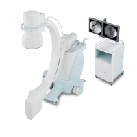
4-2-5 Setting of PCBs (XCONT etc.)
Ⅰ
XCONT 2002 PCB
Please set each jumpers to O side of Table. 4-2.
SW name Silkscreen Setup Means
「 ON 」 ○ Standard
JP1
「 KC 」 KC signal is outputted to the terminal X2
「 C/C1 」 ○ For High Voltage Trans D125PH-C/C1
JP2
「 C2 」 × For High Voltage Trans D125PH-C2
「 S 」 ○ Master reset time Approx. 1.4 sec
JP3
「 L 」 × Master reset time Approx. 3.3 sec
Table. 4-2 Jumper switch setup
Fig. 4-9 Location of jumper switch on XCONT board
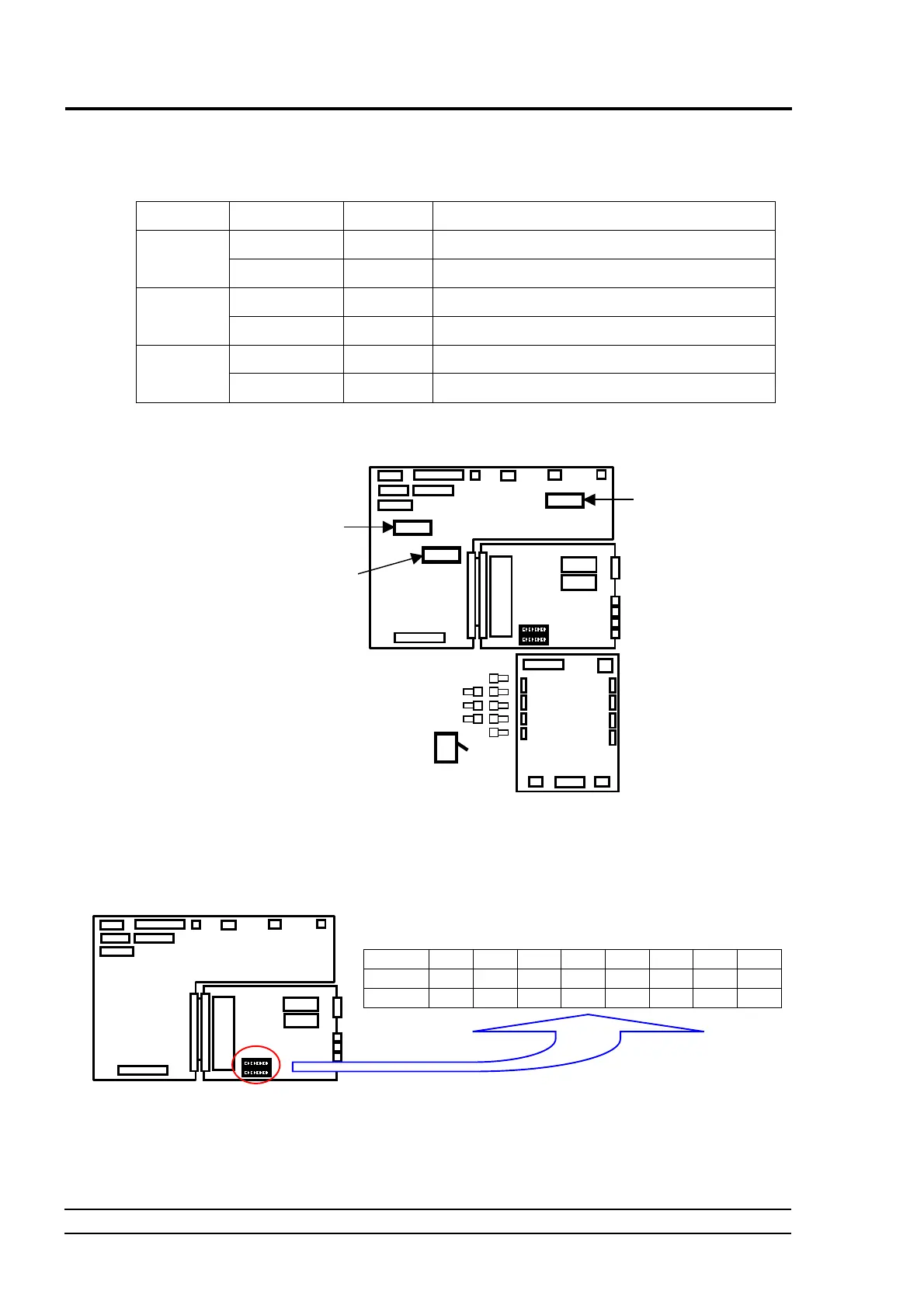
Ⅱ
NEXSC PCB
Set the DIP switch SW2 and SW3 as below for normal use mode without any option.
(Set SW2-4 to ON when you attach Remote Control option.)
1 2 3 4 5 6 7 8
SW2 ON ON OFF OFF OFF OFF OFF OFF
SW3 OFF OFF ON OFF OFF OFF OFF OFF
Fig. 4-10 Setting the DIP Switch on the NEXSC PCB (for normal use mode)
Ⅲ
INVERTER UNIT PCB
Set the DIP switch SW1-1 to OFF(“MUX-100” side). (SW1-2 is not used.)
NEXS
CP
MU Driver-2
JP1
JP2
JP3
XCON
XCONT
NEXSC CPU

 Loading...