= =I 0 I=
=CI
co,
'n 1.1
-
Y
I fr
LL
1
,
, '
L -f.
S. L7
0
(
=)
4 INSTALLATION AND MAINTENANCE/INSPECTION
MUX-100 SERVICE MANUAL 4 - 12
4-2-7 Initial setting
Ⅰ
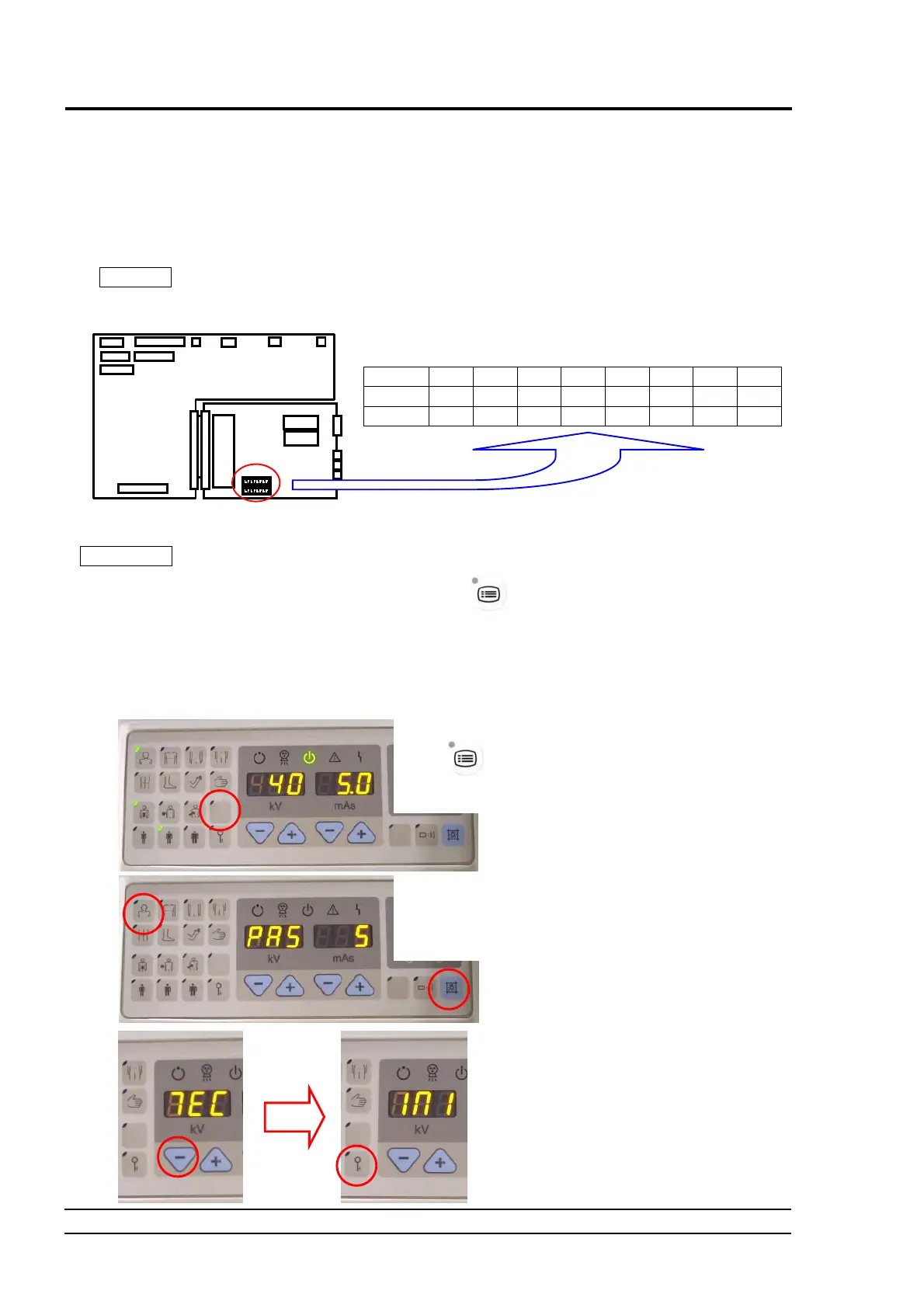
Setting the DIP switch
In order to perform the initial setting, open the right side cover of the control unit (Refer to “6-1 How to Remove
Covers”.), set to ON the DIP switch SW2-8 on the NEXSC (CPU) PCB inside the control unit (Refer to
Fig.4-14.), then turn on the power.
NOTE
When the initial setting is finished, turn off the power and return the DIP switch to OFF.
If no option will be installed, attach the right side cover.
1 2 3 4 5 6 7 8
SW2 - - - - - - - ON
SW3 - - - - - - - -
Fig. 4-14 Setting the DIP Switch on the NEXSC PCB (for Initial Setting)
Reference
You can perform the initial setting without setting to ON the DIP switch on the NEXSC PCB.
At first, press and hold the user setting switch for 3 seconds to change into user setting mode.
When “PAS” is displayed, press the head scan key and the collimator lamp key consecutively in this
order within 3 seconds (Do not confuse the keys.). When “TEC” (indicating the adjustment
mode) is displayed in the tube voltage display unit, change the display to “INI” (indicating the initial
setting mode) using the tube voltage setting keys. At the end, press the registration key. Then, the
system is set to the initial setting mode without setting to ON the DIP switch.
XCONT
NEXSC CPU
①
At first, press and hold the user settin
switch
for 3 seconds to chang
into user setting mode.
③
②
When “PA
” is displayed, press th
head scan key and the collimator lam
key consecutively in this order within 3
seconds.
W
en “TEC” is displayed, change th
display to “INI” (indicating the initia
setting mode) using the tube voltag
setting keys. Then, press th
registration key.
④
⑤
 Loading...