L
6 ADJUSTMENT/REPLACEMENT OF EACH PART
MUX-100 SERVICE MANUAL 6 - 15
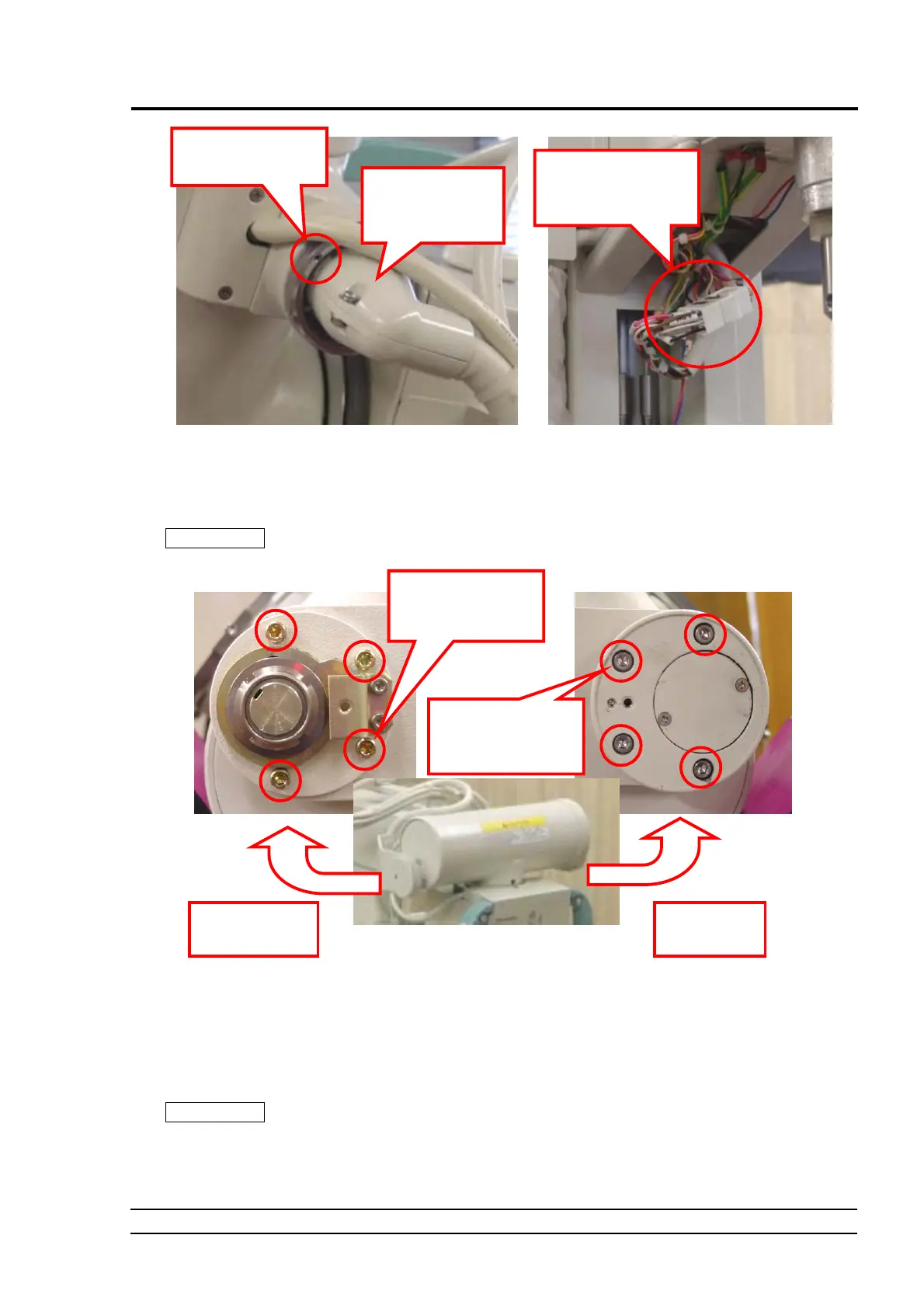
Fig. 6-24 Disconnecting the High Voltage Cable Fig. 6-25 Connector Relay Area
4. Remove the cover from the tube rotation unit attaching the tube to the arm, remove socket head cap screws (in 4
positions on each of the left and right sides) inside, then remove and move down the tube from the holding frame.
CAUTION
The weight of the tube ASSY is approximately 13 kg. Pay rigid attention in moving it down
from the arm.
Fig. 6-26 Tube Holder
5. Remove the left and right tube rotation units from the tube.
As to the right side, loosen the U nut (new type lock nut not requiring a inner clip washer) in the center, then
remove the rotation stopper, the spring washer, etc. After that, remove socket head cap screws from the shaft area,
then remove the shaft area.
As to the left side, remove the cover (countersunk head screws in 2 positions), then remove socket head cap screws
from the inside.
CAUTION
Grease will be applied on sliding units at the end. Every time removing each part, clean the
sliding units. Moreover, please be sure to decompose at the time of decomposition work,
performing marking so that an attachment position and a direction may be known from back. It
mistakes, and when assembling, it may not operate normally.
Loosen these screws,
and remove this ring.
It is recommende
for easier work t
remove this angle.
Disconnect the lo
voltage cable connecto
relayed here.
Remove these socke
head cap screws (in
positions).
Remove these socke
head cap screws (in
positions).
Rotation unit o
the right side
Rotation uni
on the left side
 Loading...