Shini Group
Technology & Marketing Dept
Issued by department: Date: Language: Document Name: Revision: Page:
Shini/CSC-TM
2013-11 zh-cn Shini product repair manual.doc
1.0 30 (62)
Catalog:
template:Standard_CN.dot; filename: Shini product repair manual; Printdate: 8/1/2014 1:58:00 PM; savedate: 8/1/2014 1:58:00 PM
4. The gap between the proximity switch and the barrel wall should be adjusted
in 3 ~ 6mm, no more than 8mm.
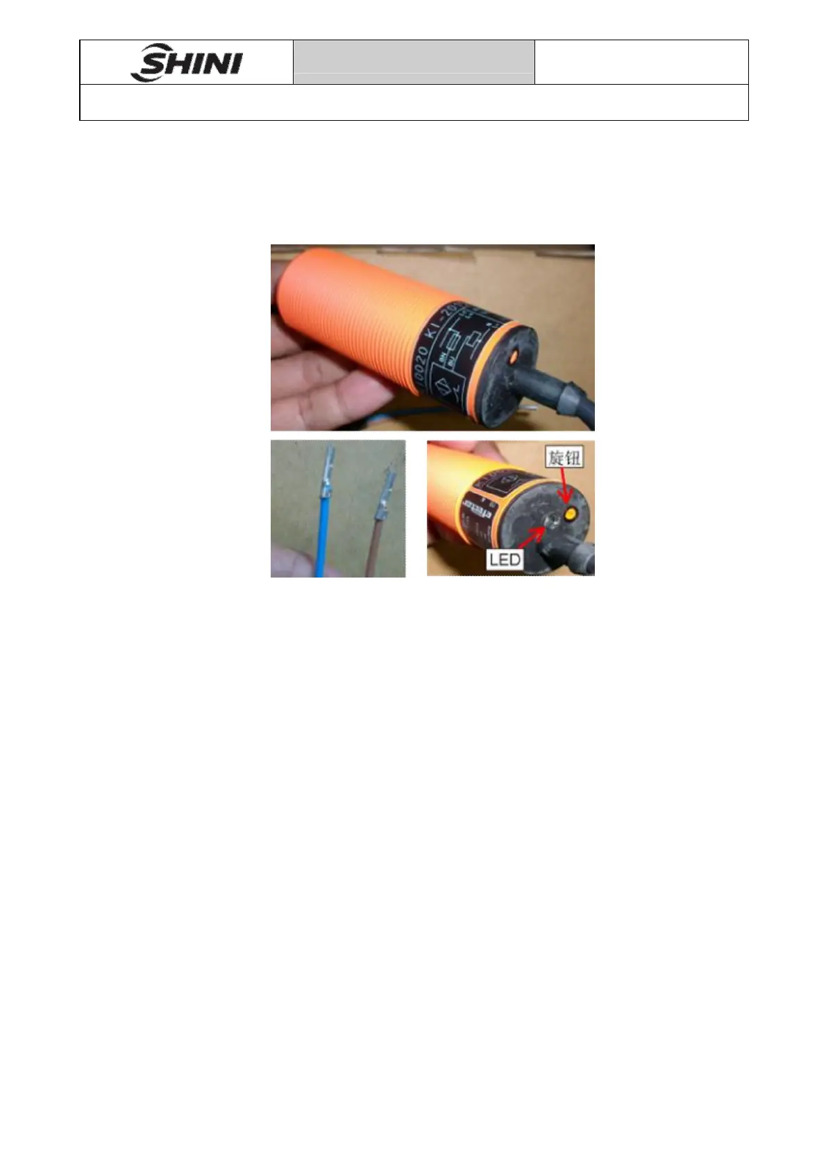
10.4 KI0020-BBOA adjustment
Pic 10-2
1. When material position is below the proximity switch, check whether the
proximity switch tail LED lights, normally the LED is ON.
2. When material position is above the proximity switch, check whether the
proximity switch tail LED lights, normally the LED is OFF.
3. Adjusting the yellow button behind it to adjust the sensitivity of sensor, the
maximum adjustable range is about 15mm.
4. Wiring connection: Acceptable power supply of sensor is 20~250VAC/DC, if
power supply is DC, it is needed to follow below method, blue wire—connect
to V-, brown wire—connect to V+)
5. The gap between the proximity switch and the barrel wall should be adjusted
in 3 ~ 6mm, no more than 8mm.