Shini Group
Technology & Marketing Dept
Issued by department: Date: Language: Document Name: Revision: Page:
Shini/CSC-TM
2013-11 zh-cn Shini product repair manual.doc
1.0 53 (62)
Catalog:
template:Standard_CN.dot; filename: Shini product repair manual; Printdate: 8/1/2014 1:58:00 PM; savedate: 8/1/2014 1:58:00 PM
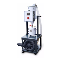
17.2 Injection/ Extruder Mode Wiring Changing
SCM can be used for injection mode (the factory has connected) and extruder mode,
but PCB board wiring is slightly different, to be confirmed before use, specific wiring
as follows:
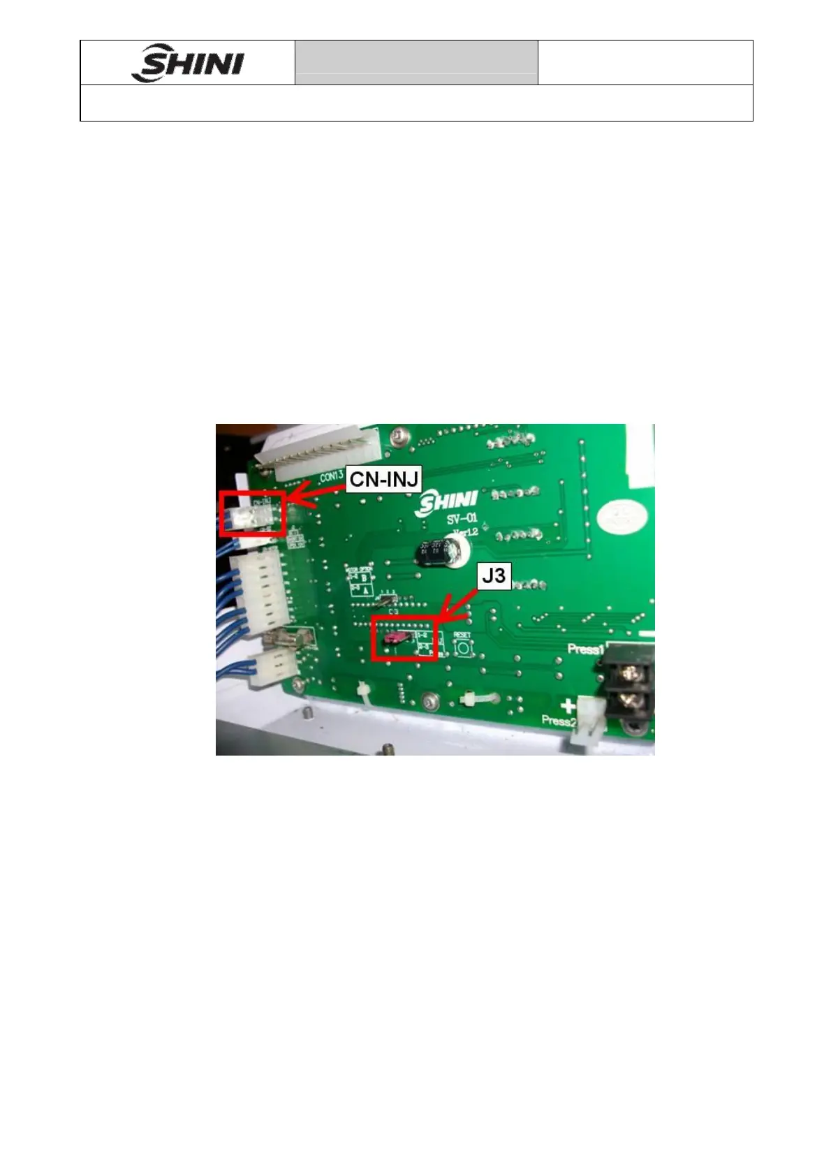
Injection mode wiring
1) CN-INJ pin 1 is connected to the negative of injection machines melt signal (0 ~
24VDC), and CN-INJ pin 2 is connected to the positive of injection machines melt
signal.
2) Shorten pin 1 and pin 2 of J3.
Pic 17-1