Operating Instructions Chapter 4
C4000 Standard/Advanced
8009861/WA65/2012-06-12 © SICK AG • Industrial Safety Systems • Germany • All rights reserved 25
Subject to change without notice
Configurable functions
4.5 Signal output (ADO)
T
he C4000 has a signal output (ADO) that can be configured. With the aid of the signal
output, the safety light curtain can signal specific states. You can use this output for a
relay or a PLC.
You must not use the signal output for safety-relevant functions!
You are only allowed to use the signal output for signalling. You must never use the signal
output for controlling the application or with safety-relevant functions.
The connection can signal one of the following states:
Assignment Possible uses
Contamination Eases diagnostics in case of soiled front screen
OSSD status with
delay of [s]
Signals the status of the switching outputs. If the safety light
curtain switches to red, then it signals the status immediately. If
it switches to green, then it signals the status only after an
adjustable delay in the range from 0.1 to 3.0 seconds.
Status of the
emergency stop
Signal is present if the button connected to the emergency stop
input on the C4000 has been pressed.
Protective field free Signal is present if no invalid interruption has occurred.
I.e. the protective field must be clear in protective operation.
Device symbol C4000 Host (receiver), context menu Configuration draft, Edit, file card
General, option Assignment of the signal output.
The electrical connection of a PLC/controller to the signal output is described in chapter
6.11 “Signal output (ADO)” on page 61.
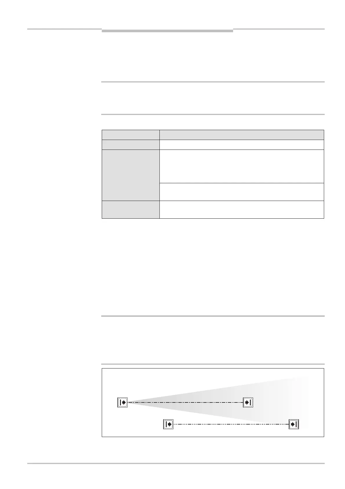
4.6 Beam coding
If several safety light curtains operate in close proximity to each other, the sender beams
of one system may interfere with the receiver of another system. With code 1 or 2 activat-
ed, the receiver can distinguish the beams designated for it from other beams. The follow-
ing settings are available: non-coded, code 1 and code 2.
Use different beam codings if the systems are mounted in close proximity!
Systems mounted in close proximity to each other must be operated with different beam
codings (code 1 or code 2). If this precaution is neglected, the system may be impaired in
its protective function by the beams from the neighbouring system and so change to the
unsafe state. This would mean that the operator is at risk.
WARNING
ration for the signal output
WARNING
the beam coding

 Loading...
