Chapter 6 Operating Instructions
C4000 Standard/Advanced
52 © SICK AG • Industrial Safety Systems • Germany • All rights reserved 8009861/WA65/2012-06-12
Subject to change without notice
Electrical installation
The two outputs are protected against short-circuits to 24 V DC and 0 V. When the light
path is clear, the signal level on the outputs is HIGH DC (at potential), when the light
beams are interrupted or there is a device fault the outputs are LOW DC.
The safety light curtain C4000 meets the interference suppression requirements (EMC)
for industrial use (interference suppression class A). When used in residential areas it
can cause interference.
To ensure full electromagnetic compatibility (EMC), functional earthing (FE) must be
connected.
The external voltage supply of the devices must be capable of buffering brief mains
voltage failures of 20 ms as specified in EN 60204C1. The power supply unit must
provide safe isolation (SELV/PELV). Suitable power supplies are available as
accessories from SICK (see section 12.7 “Accessories” on page 111).
System connections and extension connections in a cascaded system must be connect-
ed only if the system is off line. The configuration connection however, may be
connected/disconnected with the system on line.
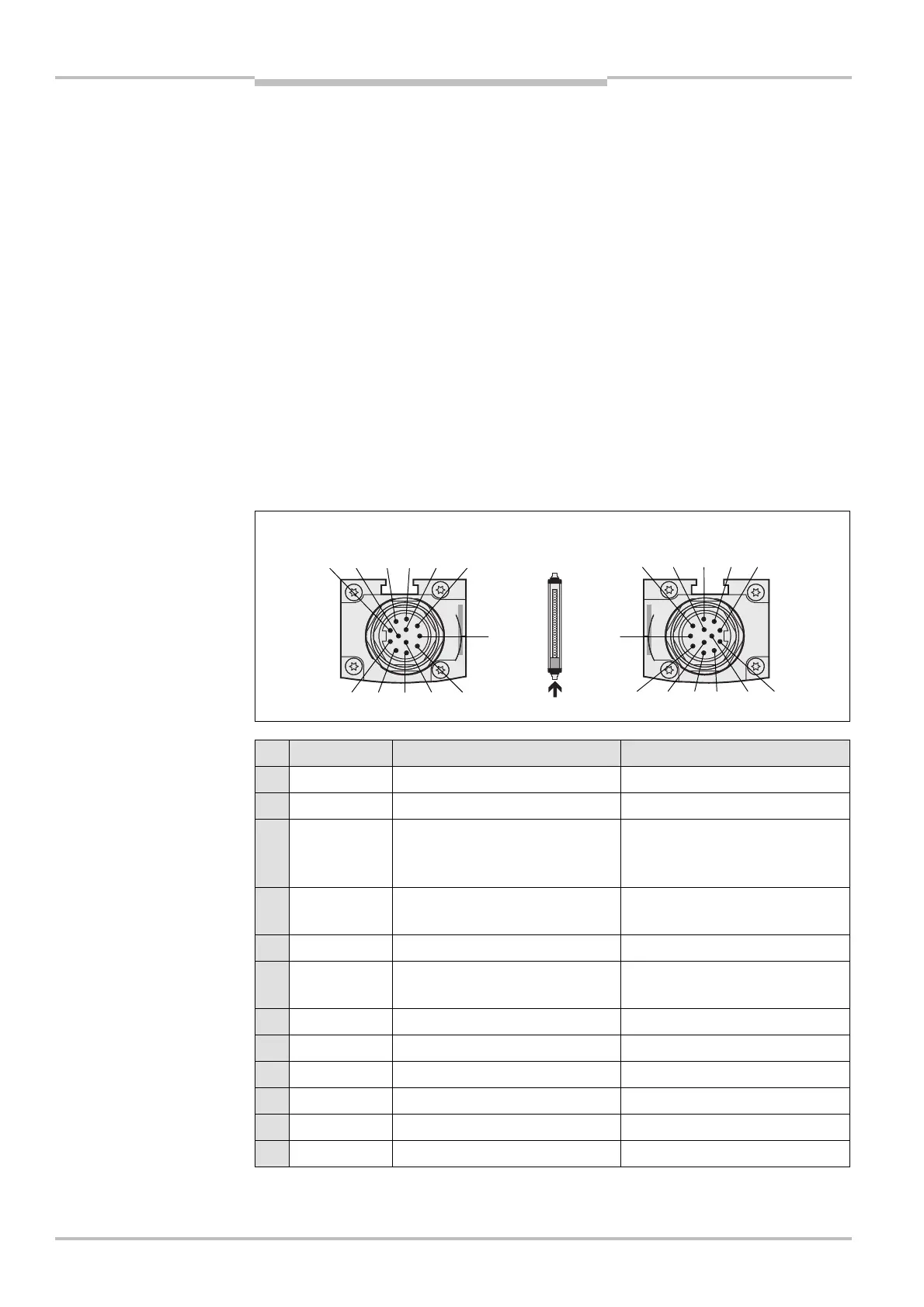
6.1 System connection M26× 11 + FE
Pin Wire colour Sender Receiver
1 Brown 24 V DC input (voltage supply) 24 V DC input (voltage supply)
2 Blue 0 V DC (voltage supply) 0 V DC (voltage supply)
3 Grey Test input:
0 V: external test active
24 V: external test inactive
OSSD1 (output signal switching
device 1)
4 Pink Reserved OSSD2 (output signal switching
device 2)
5 Red Reserved Reset/restart
6 Yellow Reserved External device monitoring
(EDM)
7 White Reserved Signal output (ADO)
8 Red/blue Reserved Output Reset required
9 Black Device communication (EFI
A
) Device communication (EFI
A
)
10 Purple Device communication (EFI
B
) Device communication (EFI
B
)
11 Grey/pink Input host/guest SEL Input host/guest SEL
FE Green Functional earthing Functional earthing
Notes
system connection
M26
× 11 + FE
system connection
M26
× 11 + FE