Operating Instructions Chapter 7
C4000 Standard/Advanced
8009861/WA65/2012-06-12 © SICK AG • Industrial Safety Systems • Germany • All rights reserved 63
Subject to change without notice
Commissioning
7 Commissioning
Commissioning requires a thorough check by qualified safety personnel!
Before you operate a system protected by the C4000 safety light curtain for the first time,
m
ake sure that the system is first checked and released by qualified safety personnel.
Please read the notes in chapter “On safety” on page 10.
7.1 Display sequence during power-up
After the system is activated, sender and receiver go through a power-up cycle. The
7Csegment display indicates the device status during the power-up cycle.
The display values have the following meaning:
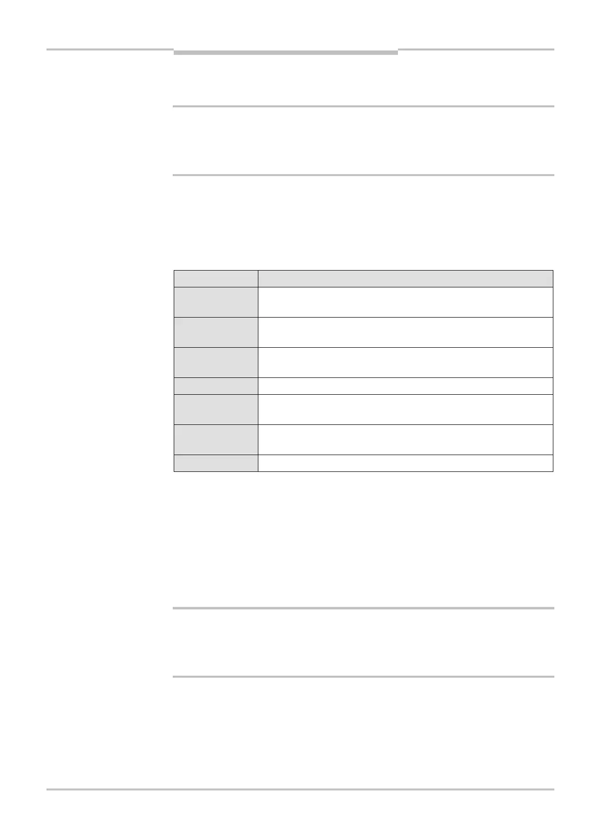
Display Meaning
, , , ,
, , ,
Testing the 7Csegment display. All segments are activated
sequentially.
Ca. 0.5 s. Is displayed only at the receiver and only in operation with
large scanning range.
, or Only on cascaded systems: Ca. 0.5 s. System operates as host ()
or as guest 1 () or guest 2 ().
, or Ca. 0.5 s. Non-coded operation or operation with code 1 or 2.
No display
or
The device is operational. Display appears if the device is
operated with reduced resolution and/or with blanking.
, or Receivers only: Receiver-sender alignment incorrect (see “Aligning
sender and receiver”).
Other display Device error. See “Fault diagnosis” on page 68.
7.2 Aligning sender and receiver
After the light curtain has been mounted and connected, the sender and receiver must be
aligned in relation to each other. The light beams emitted by the sender must hit the re-
ceiver with pin-point accuracy.
If you wish to align a cascaded system, always align the individual systems in the following
sequence: host, guest 1, guest 2.
How to align sender and receiver in relation to each other:
Secure the plant/system. No dangerous movement possible!
Make sure that the dangerous state of the machine is (and remains) switched off! During
the alignment process, the outputs of the safety light curtain are not allowed to have any
effect on the machine.
Loosen the clamping bolts which hold the light curtain in place.
Switch on the power supply to the light curtain.
Watch the alignment information on the 7Csegment display of the receiver (see Tab. 21).
Correct the alignment of the sender and receiver, until the 7Csegment display goes off.
Using the clamping bolts, fix the light curtain in place.
WARNING
during the power-up cycle
Note
WARNING