Operating Instructions Chapter 6
C4000 Standard/Advanced
8009861/WA65/2012-06-12 © SICK AG • Industrial Safety Systems • Germany • All rights reserved 55
Subject to change without notice
Electrical installation
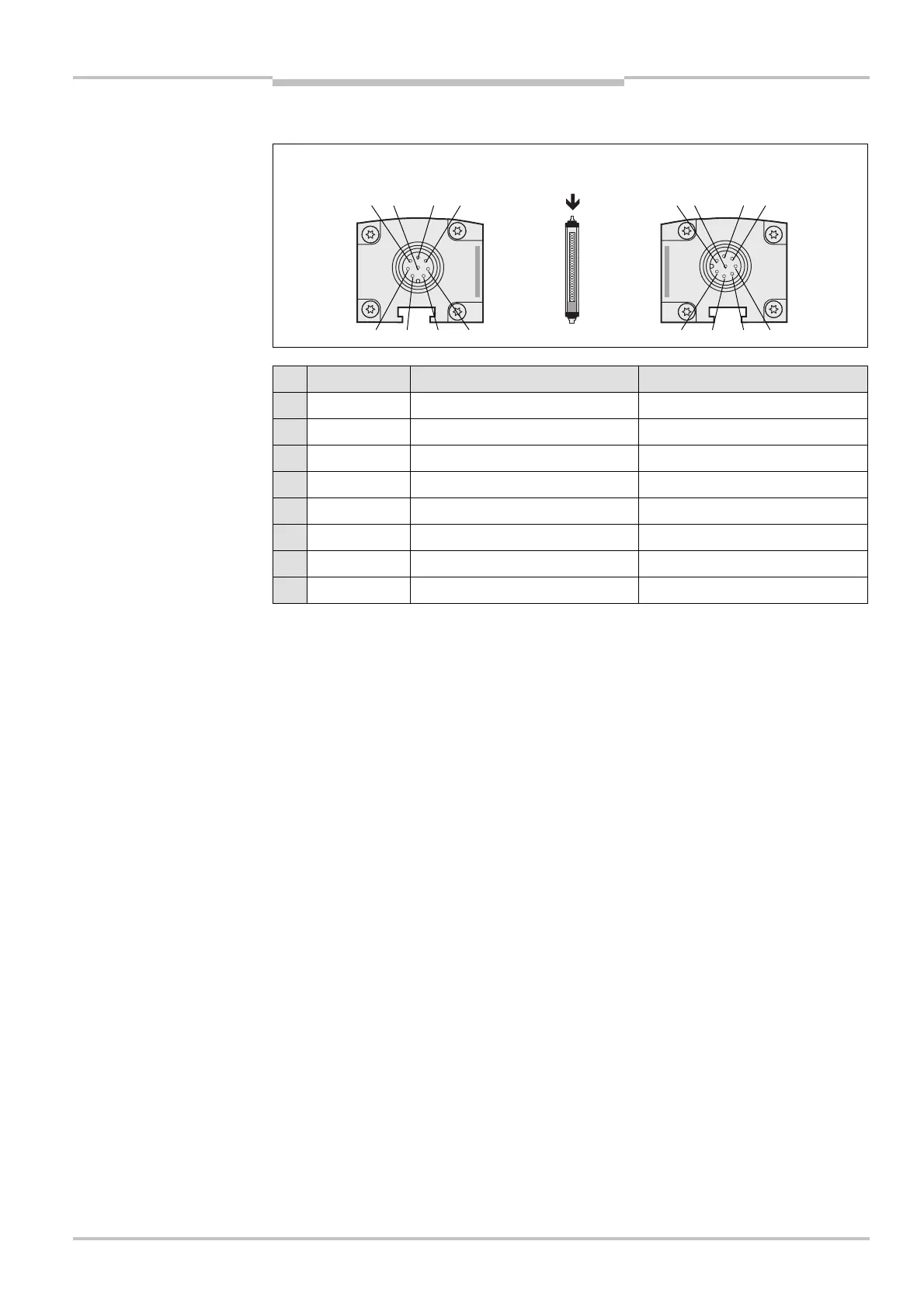
6.4 Extension connection M12× 7 + FE
Pin Wire colour Sender Receiver
1 White Output host/guest SEL Output host/guest SEL
2 Brown 24 V DC output (voltage supply) 24 V DC output (voltage supply)
3 Green Device communication (EFI
A
) Device communication (EFI
A
)
4 Yellow Device communication (EFI
B
) Device communication (EFI
B
)
5 Grey Reserved Reserved
6 Pink Reserved Reserved
7 Blue 0 V DC (voltage supply) 0 V DC (voltage supply)
FE Screen Functional earthing Functional earthing
As there are fewer pins, the following connection options are not available on an extension
connection M12× 7 + FE for the C4000:
reset button (can only be connected in the control cabinet)
teach-in key-operated switch (can only be connected in combination with a SICK
switching amplifier; further information can be found in the operating instructions for
the switching amplifier)
key-operated pushbutton for bypass
emergency stop
extension connection
M12
× 7 + FE
extension connection
M12
× 7 + FE
Note

 Loading...


