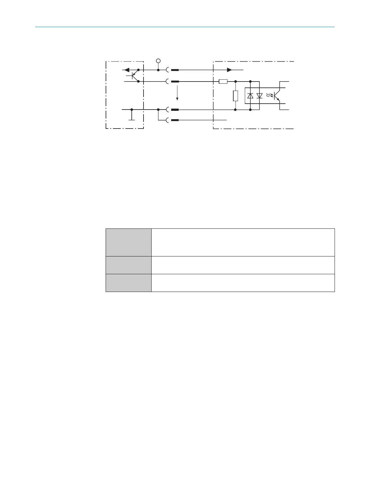
6.4.2 Wiring the switching input (CLV61x-Dx52x only)
Signal 3
3.32K
6.64K
"
§
$
Sensor GND
V
S
2
V
S
V
S
V
in
5
!
PNP sensor 1
GND
Switching input 4
GND
V
S
Figure 25: Wiring the switching input
1
Trigger sensor (PNP sensor)
2
Supply voltage V
S
(V
S
= U
V
)
3
Input signal
4
Switching input of the device (“Sensor 1”)
5
Input voltage V
in
(V
in
= U
e
)
!...$
For pin assignment, see respective device
If you would like an external sensor to trigger the read operation of the device, connect
the trigger sensor to the “Sensor 1” switching input.
Table 8: Connecting the switching input according to the application
Switching behav‐
ior
Current to input starts the internal reading interval of the device.
•
Default: Active high
•
Debouncing: Max. 10,000 ms (standard 10 ms)
Properties
•
Opto-decoupled, reverse polarity protected
•
Can be wired with PNP output of a trigger sensor
Electrical values
•
Low: | V
in
| ≤ 2 V; | I
in
| ≤ 0.3 mA
•
High: 6 V ≤ | V
in
| ≤ 32 V; 0.7 mA ≤ | I
in
| ≤ 5 mA
ELECTRICAL INSTALLATION 6
8017842/ZOK7/2019-02-01 | SICK O P E R A T I N G I N S T R U C T I O N S | CLV61x DualPort (PROFINET)
41
Subject to change without notice
 Loading...


