5.4.2 Installing the sample gas line
5.4.2.1 Laying the sample gas lines
Overview
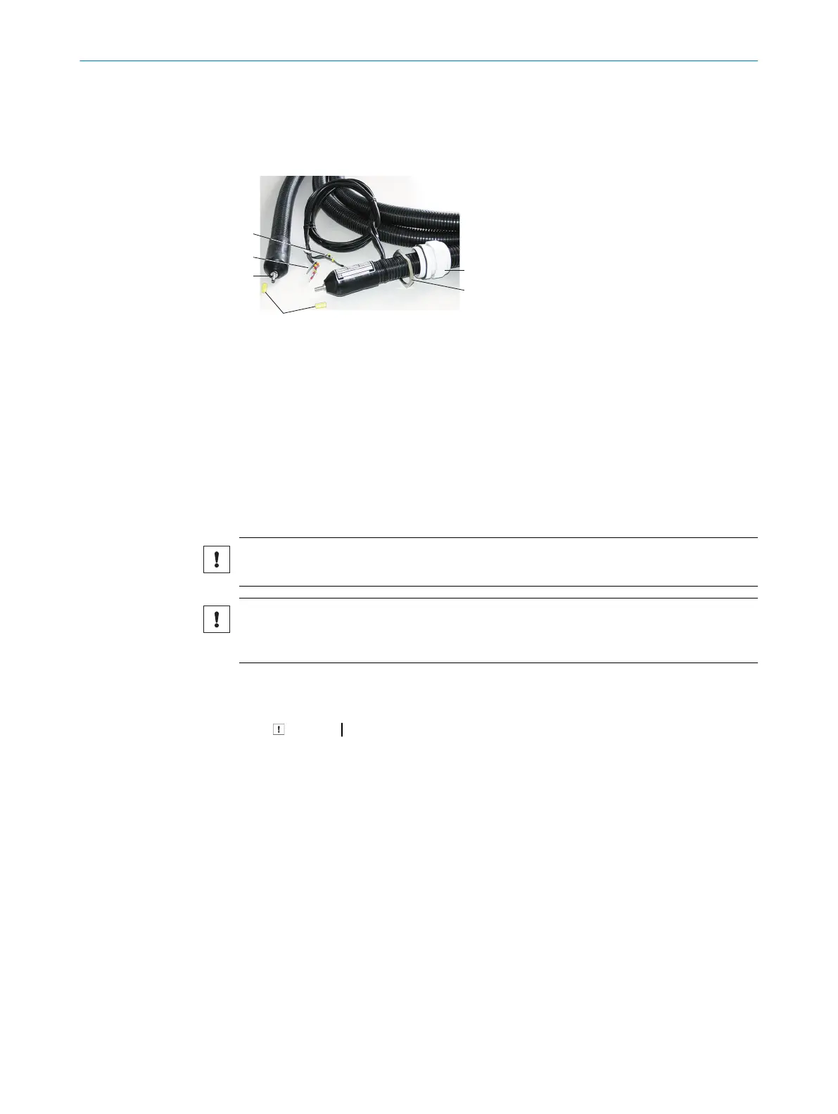
Figure 6: Heated sample gas line
1
Connection to gas sampling unit (without electrical connections)
2
Connection to measuring device (with electrical connections)
3
Protective cap
4
PT100 connections
5
Power supply
6
Cable gland
7
Locknut
Important information
NOTICE
Protect the line from damage (chafing through vibration, mechanical load).
NOTICE
The sample gas line must not be insulated at the position of the PT100 or led through a
wall, as otherwise the sample gas line may be damaged.
Procedure
1. Lay the end with the electrical connection to the measuring device.
NOTICE The screw connection for the housing duct must be located at the
same end as the electrical connection (measuring device side).
2. Lay the end without electrical connection to the gas sampling unit.
3. Observe a minimum bending radius of 300 mm.
5 MOUNTING
24
O P E R A T I N G I N S T R U C T I O N S | MCS200HW 8021889/1D1T/V3-1/2021-09 | SICK
Subject to change without notice