Important information
NOTICE
•
Install an external power disconnection unit which disconnects all connectors and
fuses near the analyzer.
•
The power disconnection unit must be marked clearly and be easily accessible.
•
The onsite wiring system to the power source of the system must be installed and
fused according to the relevant regulations.
•
Always connect a protective ground to PE.
Procedure
1. Guide the electric lines through the screw connections of the housing.
2. Connect the electric lines.
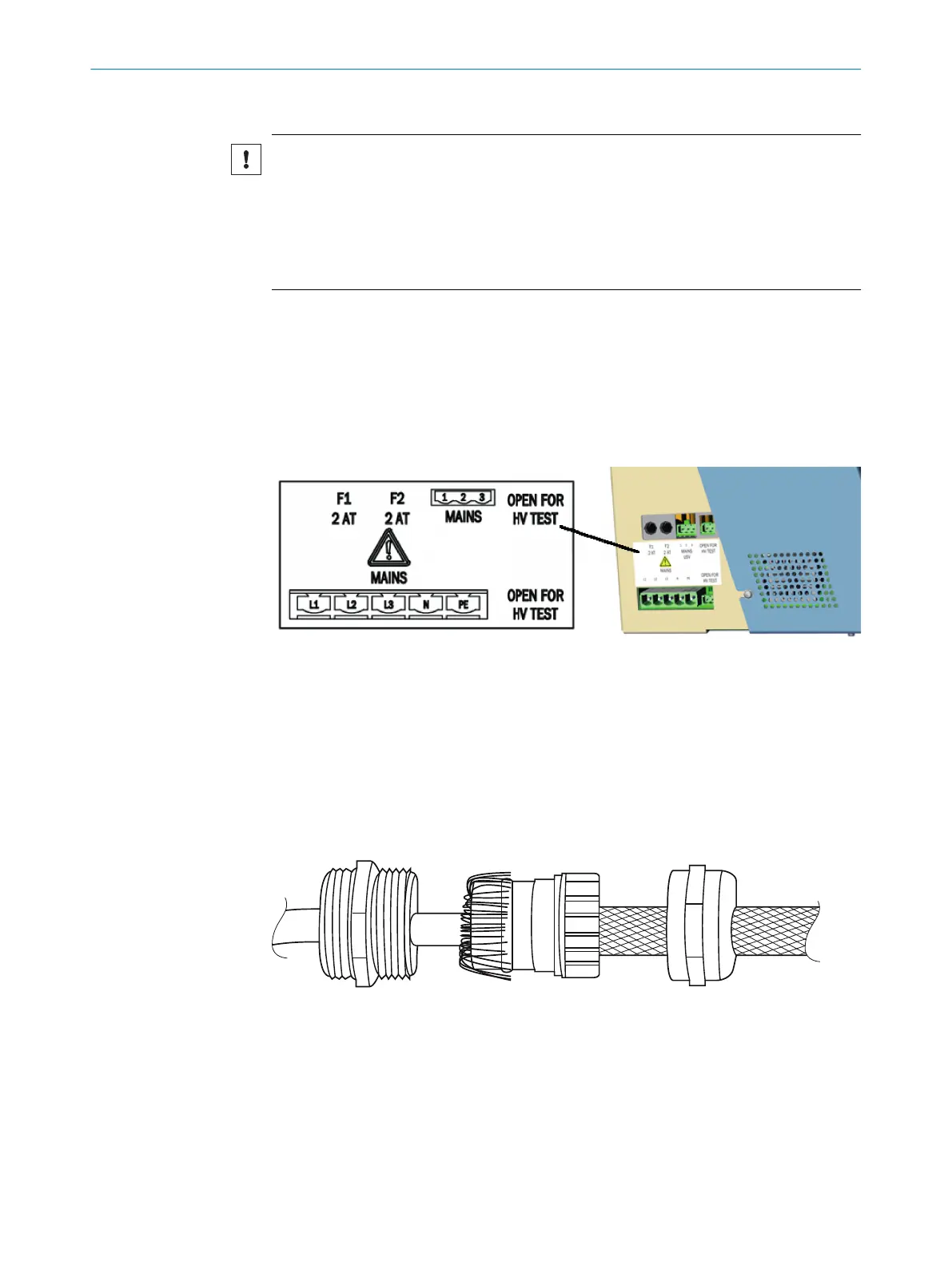
6.6 Performing a high voltage test
Overview
Figure 13: Power supply connections
Procedure
1. To avoid erroneous measurements during a high-voltage test, the bridges descri‐
bed in Figure see figure 13, page 32 must be removed.
2. Insert the bridges again after the high-voltage test.
6.7 Connecting the signal line (option)
Overview
Figure 14: Signal lines connections (shielded)
Connect the signal lines according to the wiring diagram.
Procedure
1. Guide the line through the housing duct.
2. Attach the shielding according to the Figure see figure 14, page 32
6 ELECTRICAL INSTALLATION
32
O P E R A T I N G I N S T R U C T I O N S | MCS200HW 8021889/1D1T/V3-1/2021-09 | SICK
Subject to change without notice