Figure 10: Lines – clearance and bending radius
3. Fasten the hose bundle line accordingly (e.g. on cable trays).
5.4.6 Connecting the signal lines on the analyzer
Connect the signal lines according to the wiring diagram.
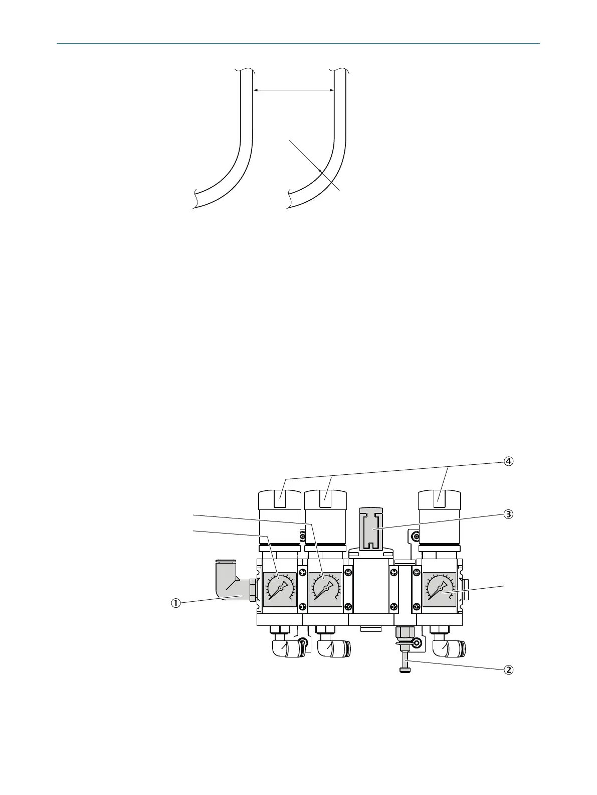
5.4.7 Setting the pressure reducer module
Overview
The external air supply is fitted on the pressure reducer module.
The instrument air is used as both induction air for the ejector (cell) and zero/control
air.
There are two possibilities of connecting instrument air:
•
One (1) shared instrument air supply for ejector air and zero/control air (inlet 1)
•
Separate instrument air supply for:
°
Ejector air (inlet 2)
°
and zero/control air (inlet 1)
10
0
BAR
10
0
BAR
10
0
BAR
3 bar
6 bar
4 bar
1
Inlet of instrument air with zero gas quality
2
Inlet of instrument air solely as induction air for ejector
3
Manual valve for instrument air selection (closed position)
4
Pressure reducer (adjustable)
MOUNTING 5
8021889/1D1T/V3-1/2021-09 | SICK O P E R A T I N G I N S T R U C T I O N S | MCS200HW
27
Subject to change without notice