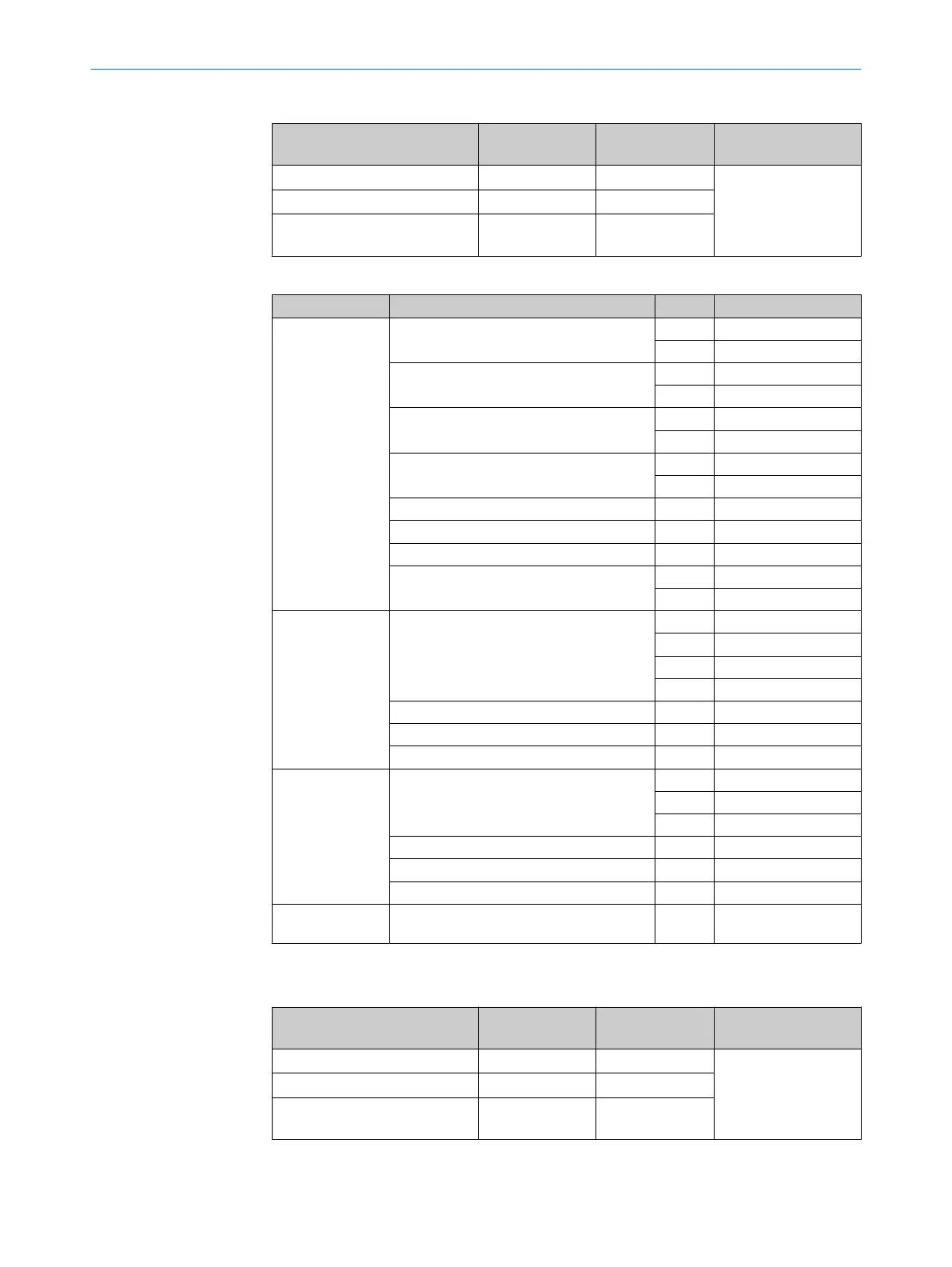
Table 28: Connection terminal - CAN interface, RS485 interface
Wire Cross-section in
mm
2
Cross-section in
AWG
Tightening torque Nm
rigid 0.14 ... 1.5 28 ... 16
0.22 ... 0.25
flexible with ferrules 0.25 ... 1.5 26 ... 16
flexible with ferrules with insu‐
lating collar
0.25 ... 0.75 26 ... 19
Table 29: Overview - pin assignment and signals
Plug Assembly Pin Assignment
Pt100
Sample gas line 1
1 Pt100 +
2 Pt100 –
Gas sampling unit filter 1 3 Pt100 +
4 Pt100 –
Gas sampling unit probe tube 1 5 Pt100 +
6 Pt100 –
Not connected 7
8
Sample gas line 2 9, 10 As above
Gas sampling unit filter 2 11, 12 As above
Gas sampling unit probe tube 2 13, 14 As above
Sample gas line 3 15 Pt100 +
16 Pt100 –
DIGITAL
INPUTS
Digital input 1 1 + 24 V
2 + Signal
3 - Signal
4 GND
Digital input 2 5 ... 8 As above
Digital input 3 9 ... 12 As above
Digital input 4 13 ... 16 As above
DIGITAL
OUTPUTS
Digital output 1 1 NC
2 COM
3 NO
Digital output 2 4 ... 6 As above
Digital output 3 7 ... 9 As above
Digital output 4 10 ... 12 As above
VALVE
OUTPUTS
Valves Internal
1
The connections must match the connections on the gas sampling unit.
Table 30: Connection terminal - PT100 signal inputs, DI, DO on analyzer
Wire Cross-section in
mm
2
Cross-section in
AWG
Tightening torque Nm
rigid 0.2 ... 2.5 24 ... 12
0.5 ... 0.6
flexible with ferrules 0.25 ... 2.5 26 ... 12
flexible with ferrules with insu‐
lating collar
0.25 ... 2.5 26 ... 12
13 TECHNICAL DATA
70
O P E R A T I N G I N S T R U C T I O N S | MCS200HW 8021889/1D1T/V3-1/2021-09 | SICK
Subject to change without notice