Operating instructions Chapter 3
Flexi Classic
8011509/YPP0/2015-10-26 © SICK AG • Industrial Safety Systems • Germany • All rights reserved 23
Subject to change without notice
Product description
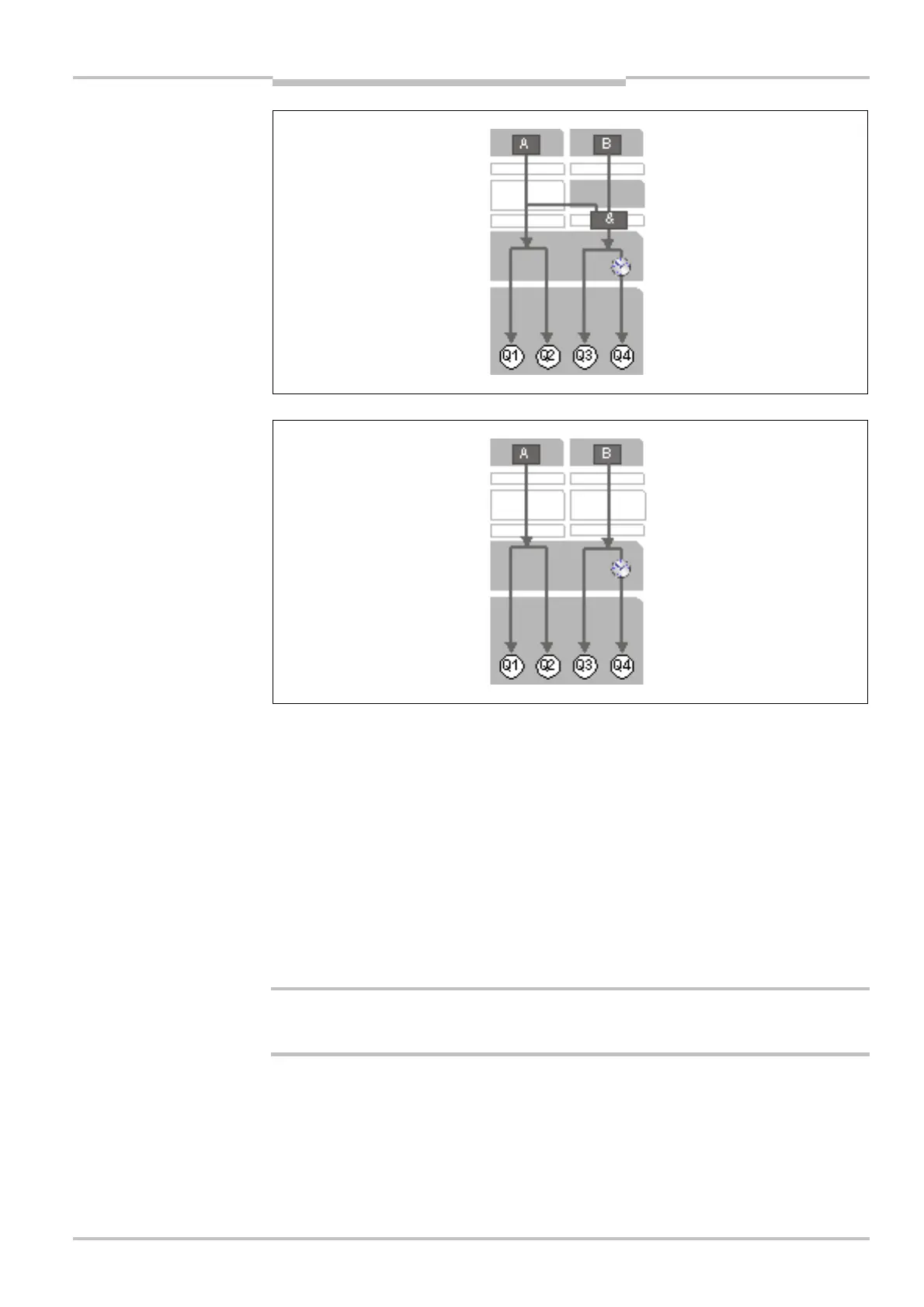
The following functions can be set by selecting the program and connecting the terminals
S1, S2, and S3 at the module:
• type of the logic and of the safety sensors to be connected
• restart interlock
• external device monitoring (EDM)
Q1 and Q2 always switch off within the response time.
Q3
1)
and Q4 can be deactivated with off delay by using the lower rotary switch (depending
on the device variant 0-5 s/0-50 s/0-300 s/not on UE410-xxxT0).
The outputs are tested periodically in order to detect errors in the safety outputs Q1-Q4.
When using XU modules see section 4.12 “Grouping of subsystems” on page 78.
For further information see section 3.6 “UE410-MU/UE410-XU programs” on page 36.
Subsequent changes to the program or to the wiring (S1-S3) without saving will result in a
safety-related shutdown.
1)
Q3 has various functions; see section 3.6 “UE410-MU/UE410-XU programs” on page 36.
programs 5-7, 9
Note
WARNING
 Loading...

