Operation
104/121 Revision 05 • INSTALLATION AND OPERATING INSTRUCTIONS • 8DJH • 500-8067.9
20 Verification of safe isolation from supply
20.1 HR or LRM plug-in sockets
➭ Remove the covers from the plug-in sockets (interfaces of phases L1, L2 and L3).
➭ Insert the HR or LRM voltage indicator consecutively into the plug-in sockets of the phases
L1, L2 and L3.
✔ If the HR or LRM voltage indicator does not flash or light up in any of the 3 phases, the
phases are not live.
➭ Refit the covers on the plug-in sockets.
DANGER
High voltage! Danger! Verify safe isolation from supply without any doubt!
➭ Possible sources of failure:
- Defective voltage indicator (or device for function testing of the coupling section)
- Maloperation of the voltage indicator (or device for function testing of the coupling
section)
➭ Test the perfect function of the voltage indicator and the coupling section in accordance
with national standards:
- On a live panel
- With a test unit according to IEC 61243-5/EN 61243-5
- On all phases
➭ Use only voltage indicators or devices according to EN 61243-5 / IEC 61243-5 /
VDE 0682-415 to test the function of the coupling section. (The interface conditions have
not changed as against the old standard VDE 0681 Part 7; the corresponding indicators can
still be used.)
➭ Perform repeat test of interface conditions at the capacitive interfaces, as well as on the
indicators according to the customer's specifications or national standards.
➭ Do not use short-circuiting jumpers as separate plugs. The function of the surge arrester
installed is not guaranteed anymore if short-circuiting jumpers are used (see page 23,
"Voltage detecting systems").
NOTE
The following descriptions do not substitute reading the manufacturer documentation.
➭ Before using the voltage detecting systems, read the supplied manufacturer
documentation.
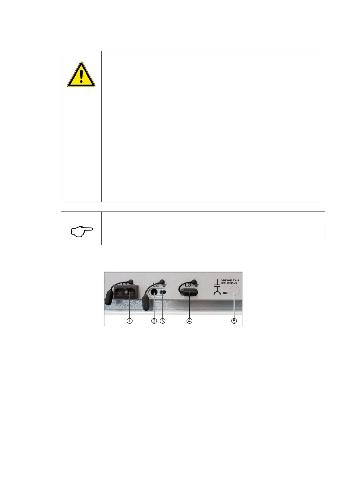
①
Voltage indicator type HR
②
Capacitive test socket, phase L2
③
Earth socket
④
Cover for test sockets
⑤
Documentation to repeat test of
interface condition

 Loading...


