Operation
84/121 Revision 05 • INSTALLATION AND OPERATING INSTRUCTIONS • 8DJH • 500-8067.9
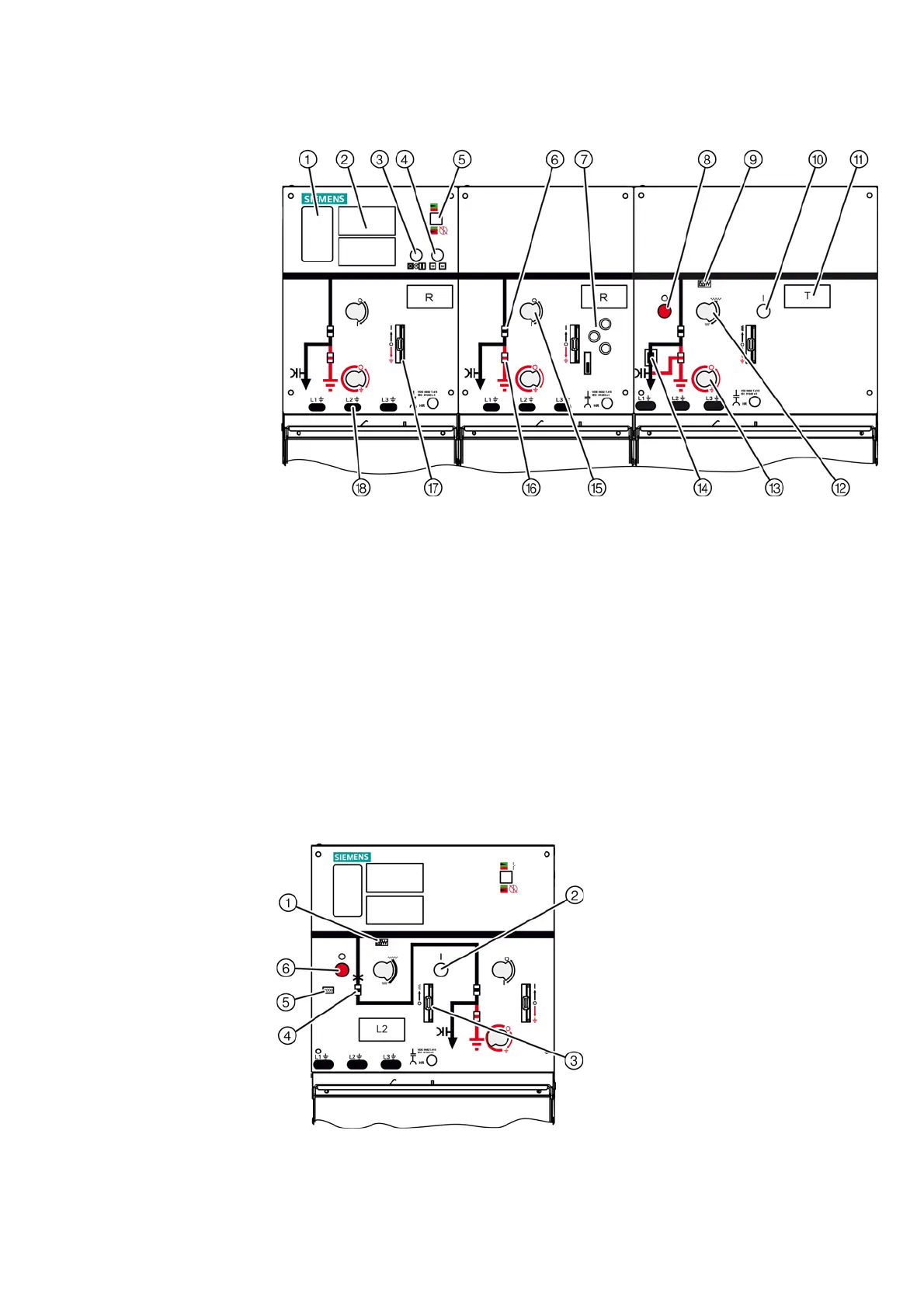
16 Indicators and control elements
Fig. 55: RRT block 8DJH
①
Rating plate
⑩
ON pushbutton for transformer feeder
②
Short-circuit indicator, earth-fault indicator,
integrated capacitive voltage detecting system
(option)
⑪
Feeder designation label
⑫
Actuating opening for "spring charging"
③
ON/OFF momentary-contact rotary control
switch for motor operating mechanism (option)
⑬
Actuating opening for CLOSING/OPENING the
earthing switch
④
Local-remote switch for motor operating
mechanism (option)
⑭
Fuse trip indicator
⑤
Ready-for-service indicator
⑮
Actuating opening for CLOSING/OPENING the
disconnector
⑥
Position indicator for disconnector
⑯
Position indicator for earthing switch
⑦
Key-operated interlock (option)
⑰
Control gate/locking device (option for three-
position switch-disconnector)
⑧
OFF pushbutton for transformer feeder
⑨
"Spring charged" indicator
⑱
Sockets for capacitive voltage detecting system
Fig. 56: 8DJH circuit-breaker panel type L2
①
"Spring charged" indicator
②
ON pushbutton for circuit-breaker
③
Control gate/locking device for circuit-breaker
④
Position indicator for circuit-breaker
⑤
Operations counter
⑥
OFF pushbutton for circuit-breaker

 Loading...


